Carrier WeatherMaker 48FE handleiding
Handleiding
Je bekijkt pagina 33 van 80
33
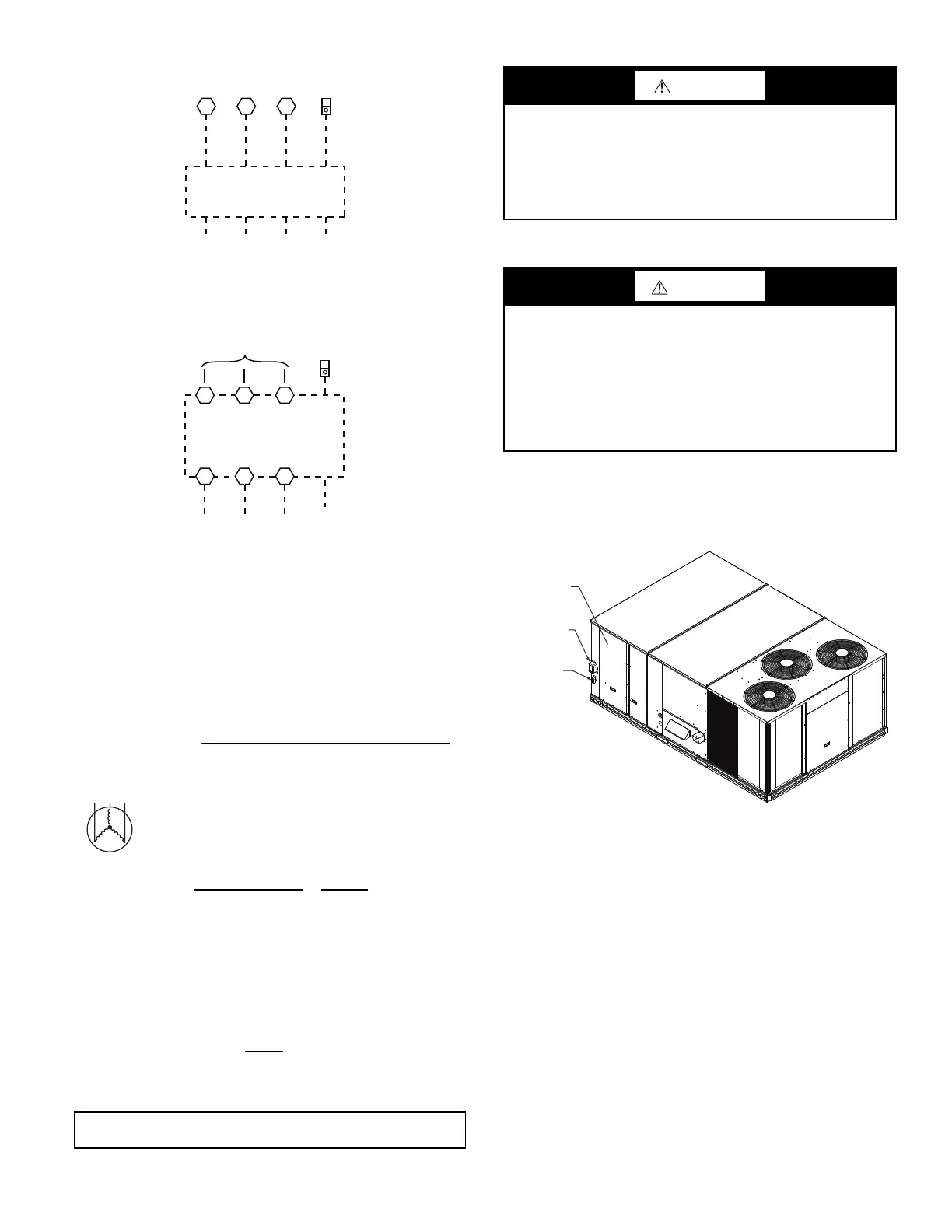
Fig. 47 — Power Wiring Connections
Provide a ground-fault and short-circuit over-current protection
device (fuse or breaker) per NEC Article 440 (or local codes).
Refer to unit informative data plate for MOCP (Maximum Over-
current Protection) device size.
Voltage to compressor terminals during operation must be within
voltage range indicated on unit nameplate. On 3-phase units, volt-
ages between phases must be balanced within 2% and the current
within 10%. Use the following formula to determine the percent
of voltage imbalance.
Example: Supply voltage is 230-3-60
Determine maximum deviation from average voltage.
(AB) 227-224 = 3-v
(BC) 231-227 = 4-v
(AC) 227-226 = 1-v
Maximum deviation is 4-v.
Determine percent of voltage imbalance.
This amount of phase imbalance is satisfactory as it is below the maximum
allowable 2%.
CONVENIENCE OUTLETS
Two types of convenience outlets are offered on 48FE models:
non-powered and unit-powered. Both types provide a 125 volt
GFCI (ground-fault circuit-interrupter) duplex receptacle rated at
15-A behind a hinged waterproof access cover, located on the pan-
el beneath the control box. See Fig. 48.
Fig. 48 — Convenience Outlet Location
Installing Weatherproof Cover
A weatherproof while-in-use cover for the factory-installed conve-
nience outlets is now required by UL standards. This cover cannot
be factory-mounted due its depth; it must be installed at unit instal-
lation. For shipment, the convenience outlet is covered with a
blank cover plate.
The weatherproof cover kit is shipped in the unit’s control box.
The kit includes the hinged cover, a backing plate and gasket.
DISCONNECT ALL POWER TO UNIT AND CONVE-
NIENCE OUTLET. LOCK-OUT AND TAG-OUT ALL
POWER.
Remove the blank cover plate at the convenience outlet; discard
the blank cover.
Loosen the 2 screws at the GFCI duplex outlet, until approximate-
ly 1/2 in. (13 mm) under screw heads are exposed. Press the gas-
ket over the screw heads. Slip the backing plate over the screw
heads at the keyhole slots and align with the gasket; tighten the
2 screws until snug (do not over-tighten).
% Voltage
Imbalance
= 100 x
max voltage deviation from average voltage
average voltage
AB = 224-v
BC = 231-v
AC = 226-v
Average Voltage =
(224 + 231 + 226)
=
681
= 227
33
% Voltage Imbalance = 100x
4
= 1.76%
227
IMPORTANT: If the supply voltage phase imbalance is more than 2%, contact
your local electric utility company immediately.
11 13
L1
L2 L3 Ground
(GR)
TB1
208/230-3-60
460-3-60
575-3-60
T1 T2 T3
L1 L2 L3
L1 L2 L3
Factory
Wiring
Disconnect
per NEC
Optional
Disconnect
Switch
12
Equip
GR Lug
Ground
(GR)
Equip
GR Lug
Units Without Disconnect Option
Units With Disconnect Option
A
B
C
MOTOR
CAUTION
UNIT DAMAGE HAZARD
Failure to follow this caution may result in equipment damage.
Operation on improper line voltage or excessive phase
imbalance constitutes abuse and may cause damage to
electrical components. Such operation would invalidate any
applicable Carrier warranty.
WARNING
ELECTRICAL OPERATION HAZARD
Failure to follow this warning could result in personal injury or
death.
Units with convenience outlet circuits may use multiple
disconnects. Check convenience outlet for power status before
opening unit for service. Locate its disconnect switch, if
appropriate, and open it. Lock-out and tag-out this switch, if
necessary.
Convenience
Outlet
Electric
Disconnect
Switch
Control Box
A
ccess Panel
Bekijk gratis de handleiding van Carrier WeatherMaker 48FE, stel vragen en lees de antwoorden op veelvoorkomende problemen, of gebruik onze assistent om sneller informatie in de handleiding te vinden of uitleg te krijgen over specifieke functies.
Productinformatie
| Merk | Carrier |
| Model | WeatherMaker 48FE |
| Categorie | Niet gecategoriseerd |
| Taal | Nederlands |
| Grootte | 10304 MB |


