Carrier WeatherMaker 48FE handleiding
Handleiding
Je bekijkt pagina 34 van 80
34
Mount the weatherproof cover to the backing plate as shown in
Fig. 49. Remove 2 slot fillers in the bottom of the cover to permit
service tool cords to exit the cover. Check for full closing and
latching.
Non-powered type
This type requires the field installation of a general-purpose 125 v
15-A circuit powered from a source elsewhere in the building. Ob-
serve national and local codes when selecting wire size and con-
duit requirements, fuse or breaker requirements and disconnect
switch size and location. Route 125 v power supply conductors
into the bottom of the utility box containing the duplex receptacle.
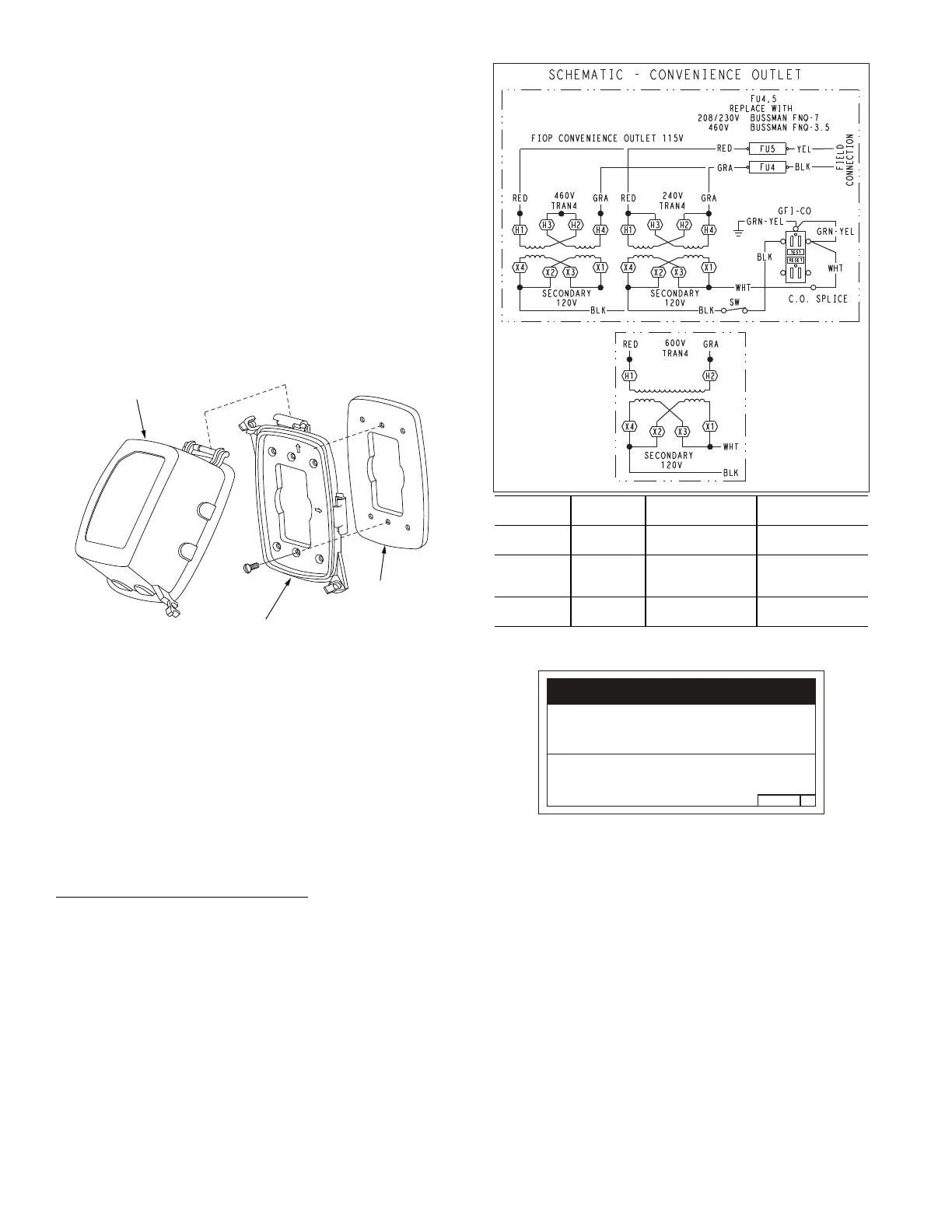
Unit-powered type
A unit-mounted transformer is factory-installed to stepdown the
main power supply voltage to the unit to 115 v at the duplex recep-
tacle. This option also includes a manual switch with fuse,
located in a utility box and mounted on a bracket behind the
convenience outlet; access is through the unit’s control box access
panel. See Fig. 48.
Fig. 49 — Weatherproof Cover Installation
The primary leads to the convenience outlet transformer are not
factory-connected. If local codes permit, the transformer primary
leads can be connected at the line-side terminals on the unit-
mounted non-fused disconnect switch; this will provide service
power to the unit when the unit disconnect switch is open. See
Fig. 50.
See Fig. 51 for convenience outlet utilization notice.
Test the GFCI receptacle by pressing the TEST button on the face
of the receptacle to trip and open the receptacle. Check for proper
grounding wires and power line phasing if the GFCI receptacle
does not trip as required. Press the RESET button to clear the
tripped condition.
Using unit-mounted convenience outlets
Units with unit-mounted convenience outlet circuits will often re-
quire that 2 disconnects be opened to de-energize all power to the
unit. Treat all units as electrically energized until the convenience
outlet power is also checked and de-energization is confirmed.
Observe National Electrical Code Article 210, Branch Circuits, for
use of convenience outlets.
FACTORY OPTION THRU-BASE CONNECTIONS
All units are equipped with the ability to bring utilities through the
base.
Gas is brought up through an embossed area located in the gas
section behind the gas entrance post. Access is gained through the
gas access panel. A knock out must be removed to accomplish
this.
Fig. 50 — Powered Convenience Outlet Wiring
Fig. 51 — Convenience Utilization Notice
The electrical entrance is located in the control box area and can
be accessed through the control box access panel. An embossed
area is provided with 3 knock outs. High voltage is brought
through the multi knock out by removing the appropriate size for
the size of the fitting required. A 7/8 in. knock out is provided for
low voltage. An additional 7/8 in. knock out is provided for a
115 volt line which is used when the unit is equipped with the non-
unit powered convenience outlet option.
All required fittings are field supplied. Install fittings when access
to both top and bottom of the base pan is available. See electrical
and gas connections for routing and connection information.
UNITS WITHOUT THRU-BASE CONNECTIONS
1. Install liquid tight conduit between disconnect and control
box.
2. Pull correctly rated high voltage wires through the conduit.
3. Install power lines to terminal connections as shown in
Fig. 47.
Cover — While-In-Use
Weatherproof
Baseplate For
GFCI Receptacle
Gasket
GFCI Receptacle
Not Included
T
O
P
TO
P
TOP
W
E
T
LOC
A
TI
O
N
S
W
E
T
L
O
C
A
TI
O
N
S
UNIT
VOLTAGE
CONNECT
AS
PRIMARY
CONNECTIONS
TRANSFORMER
TERMINALS
208,230 240
L1: RED +YEL
L2: BLU + GRA
H1 + H3
H2 + H4
460 480
L1: RED
Splice BLU + YEL
L2: GRA
H1
H2 + H3
H4
575 600
L1: RED
L2: GRA
H1
H2
2.050HE501288
NOTICE/AVIS
Convenience Outlet Utilization
Maximum Intermittent Use 15 - Amps
Maximum Continuous Use 8 - Amps
Observe a 50% limit on the circuit
Loading above 8 - Amps
Utilisation de la prise utilitaire
Usage intermittent maximum 15 - Amps
Usage continu maximum 8 - Amps
Observez une limite de 50% sur le circuit
Chargement au-dessus de 8 - Amps
Bekijk gratis de handleiding van Carrier WeatherMaker 48FE, stel vragen en lees de antwoorden op veelvoorkomende problemen, of gebruik onze assistent om sneller informatie in de handleiding te vinden of uitleg te krijgen over specifieke functies.
Productinformatie
| Merk | Carrier |
| Model | WeatherMaker 48FE |
| Categorie | Niet gecategoriseerd |
| Taal | Nederlands |
| Grootte | 10304 MB |


