Carrier Aquazone 50WD handleiding
Handleiding
Je bekijkt pagina 23 van 84
23
LOW VOLTAGE, CONTROL WIRING
Control wiring for units with Constant Torque blower motors are
connected to a terminal block located in the unit electrical box.
Refer to the unit wiring diagram for connection details.
Units without factory installed TruVu DDC controller can be con-
trolled using the included thermostat inputs (R, O, Y1, C, G) for
single stage heat pump thermostat or field-installed DDC (Direct
Digital Controls) controls. Note that the reversing valve on the
unit is energized when the unit is in the cooling mode. See Fig. 19
for typical thermostat connections.
Fig. 19 — Typical Thermostat Connections
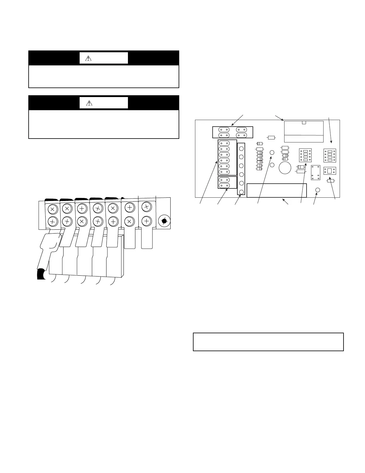
Control wiring for units with constant airflow ECM blower
motors is routed through a constant airflow ECM interface board.
Thermostat input wiring is connected to the 10-pin screw type
terminal block on the lower center portion of the ECM Interface
Board. In addition to providing a connecting point for thermostat
wiring, the interface board also translates thermostat inputs into
control commands for the Electronic Commutated Motor (ECM)
DC fan motor and displays an LED indication of operating status.
Refer to the unit wiring diagrams for complete details. See Fig. 20.
The thermostat connections and their functions are as follows.
ECM INTERFACE THERMOSTAT CONNECTIONS
• Y1 First Stage Compressor Operation
• Y2 Second Stage Compressor Operation
• G Fan
• O Reversing Valve (energized in cooling)
• W1 Auxiliary Electric Heat (runs with compressor)
• EM/W2 Emergency Heat (electric heat only)
• NC Transformer 24 Vac Common (extra connection)
• C1 Transformer 24 Vac Common (primary connection)
• R Transformer 24 Vac Hot
• H Dehumidification Mode
Fig. 20 — ECM Interface Board Physical Layout
THERMOSTAT AND DDC SENSORS
Thermostats or DDC space sensors should be located on an
interior wall away from supply ducts. Avoid locations subject to
direct sunlight or drafts, or external walls. Thermostat wiring
should be 18 AWG (American Wire Gauge). Refer to the
installation instructions for the thermostat for further details.
ADDITIONAL CONTROLS OPTIONS WIRING
Hot Gas Reheat Control
Units with hot gas reheat (HGRH) will include an additional H
terminal on the input terminal board for dehumidification con-
trol. To enable a call for dehumidification, a 24-v signal must
be sent to the H terminal with no voltage applied to the Y1 or
O terminals. Any call for cooling (Y1 and O) will override the
dehumidification call.
WARNING
To avoid possible injury or death due to electrical shock, open
the power supply disconnect switch and secure it in an open
position during installation.
CAUTION
Never route control wiring through the same conduit as power
supply wiring. Electrical noise and transients from the power
wiring can cause communication issues or damage to the
control wiring and connected control components.
C
O
Y
R
G
IMPORTANT: Exceptionally long runs of thermostat wire
should be avoided to prevent voltage drops in the control circuit.
RR
C1
C2
10
EM
W1
O
Y2
Y1
G
H
C
W2
W1
O
Y2
Y1
G
CFM
H
CFM
ADJUST
A
B
C
D
NORM
[+]
[-]
TEST
HGRH
YES
NO
HGRH
J01
R
C
G
O
Y1 Y2 W1 W2 H C
1
3
98
7
6
5
2
4
11
LEGEND
1 Motor harness plug
2 Blower CFM adjustment
3 Motor settings
4 Dehumidification indication
5 Thermostat digital contact inputs
6 Cfm count indicator
7 Thermostat input status indication
8 Reheat digital outputs
9 Thermostat outputs
10 24 Vac
11 Dehumidification method selector
Bekijk gratis de handleiding van Carrier Aquazone 50WD, stel vragen en lees de antwoorden op veelvoorkomende problemen, of gebruik onze assistent om sneller informatie in de handleiding te vinden of uitleg te krijgen over specifieke functies.
Productinformatie
| Merk | Carrier |
| Model | Aquazone 50WD |
| Categorie | Niet gecategoriseerd |
| Taal | Nederlands |
| Grootte | 15865 MB |


