Carrier Aquazone 50WD handleiding
Handleiding
Je bekijkt pagina 24 van 84
24
Pump Relay
Units with selected Pump Relay option can be field wired to en-
able a field provided loop pump or solenoid valve when there is a
call for compressor operation. Represented as AUX relay on Wir-
ing Diagrams (see Fig. 26-41).
Energy Management Switch
Units with selected energy management switch (EMS) can be
field wired to disable unit operation when a 24-v signal is removed
from the relay. Removing the 24-v signal causes the relay to open,
which cuts 24-v power to the unit control circuit. All unit compo-
nents will be disabled at when the EMS is deactivated. Represent-
ed as EMS relay on Wiring Diagrams (see Fig. 26-41).
NOTE: Units with constant torque ECM motors may experience a
30 second delay between when the EMS is activated and when the
blower finally shuts off. Constant torque ECM blowers are factory
programmed with a 30-second delay when losing the control
signal, to prevent nuisance shut downs.
Alarm Output (All Units)
If the unit is being connected to a thermostat or DDC control with
an alarm indicator, this connection is made at the unit malfunction
output on the Unit Protection Module (UPM). See the Unit
Protection Module heading in Step 9 — “Configure Unit Control
Components” on page 24 section for further details.
TruVu DDC Controller
TruVu is a factory installed DDC control that requires the use of
Carrier ZS or non-communicating sensors or the Carrier TruVu
Equipment touch interface for space temperature sensing. TruVu
DDC is not compatible with thermostats.
All units equipped with TruVu DDC controller include factory-
installed EWT, LWT, and SAT sensors. Additional field-installed
sensors should be provided and wired as needed. Please refer to
the Operation section of the Installation, Operation, and Mainte-
nance (IOM) manual for available inputs for optional field-
installed components.
All TruVu wiring is completed at the TruVu control board. See
Fig. 41 for details.
Control Transformer
All units without factory installed TruVu DDC include 75VA
transformer. All units with TruVu™ DDC controller include a
100VA transformer.
The VA capacity of the transformer should be considered when
applying low voltage accessories, such as shut off valves,
thermostats, or DDC controls. Table 12 shows the VA draw of
factory-mounted components in the low voltage heat pump. The
total VA draw of the heat pump internal components plus any at-
tached accessories must be lower than the VA capacity of the unit
control transformer.
Step 9 — Configure Unit Control Components
UNIT PROTECTION MODULE (UPM)
The Unit Protection Module (UPM) as shown in Fig. 21 is a print-
ed circuit board (PCB) included in all units, that interfaces with
the thermostat or the digital direct controller.
The main purpose of this device is to protect the compressors by
monitoring the different states of switches and sensors of each re-
frigerant circuit. This device provides time delays and protects the
unit against freezing of the water and refrigerant heat exchangers
as well as condensate overflow when the appropriate sensors are
installed.
IMPORTANT: Relocate the factory installed supply air
temperature sensor (SAT) when using a field-installed electric
heater. The Supply Air Temperature (SAT) sensor should be
downstream of any external heating device for effective
control.
CAUTION
Exceeding the transformer capacity can result in low control
voltage, erratic unit operation or damage to the heat pump.
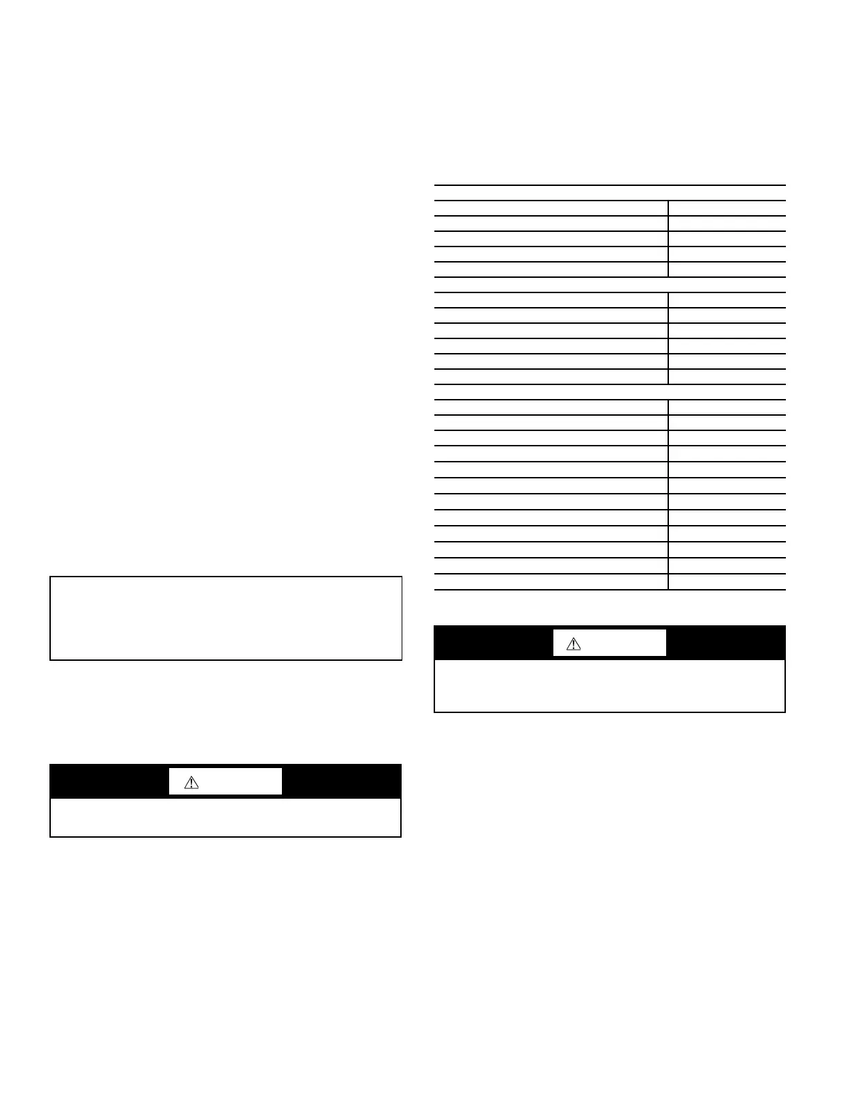
Table 12 — Low Voltage VA Draw
STANDARD CONSTRUCTION
Component VA
Reversing Valve Solenoid 12
Compressor Contactor Single Phase 10
UPM Board 5
Total VA Draw 27
OPTION CARD
Component VA
Total from ‘Standard’ 27
Option Card 5
Hot Gas Reheat Solenoid 9
Economizer Valve 3
Total VA Draw 44
OPTIONAL COMPONENTS
Component VA
Compressor Monitor Relay 4
Blower Monitor Relay 4
Energy Management Relay 4
Fire Alarm Relay 4
Heater Contactor 10
AUX Relay 10
Electric Heating/Blower Relay 4
683 TruVu™ DDC 37
CA ECM Board 1
Leaving Water Valve 7
Compressor Contactor 3 Phase 10
WARNING
To avoid possible injury or death due to electrical shock, open
the power supply disconnect switch and secure it in an open
position during installation.
Bekijk gratis de handleiding van Carrier Aquazone 50WD, stel vragen en lees de antwoorden op veelvoorkomende problemen, of gebruik onze assistent om sneller informatie in de handleiding te vinden of uitleg te krijgen over specifieke functies.
Productinformatie
| Merk | Carrier |
| Model | Aquazone 50WD |
| Categorie | Niet gecategoriseerd |
| Taal | Nederlands |
| Grootte | 15865 MB |


