Carrier Aquazone 50WD handleiding
Handleiding
Je bekijkt pagina 13 van 84
13
If the unit will be installed in a new installation with new
ductwork, the installation should be designed using current
ASHRAE (American Society of Heating, Refrigerating, and Air-
Conditioning Engineers) procedures for duct sizing. If the unit will
be connected to an existing duct system, a check should be made
to assure that the duct system has the capacity to handle the air
required for the unit application. If the duct system is too small,
larger ductwork must be installed. Be certain to check for existing
leaks and repair. The duct system and all diffusers should be sized
to handle the designed airflow quietly. To maximize sound attenu-
ation of the unit blower, the supply and return air plenums should
be insulated. There should be no direct straight air path through
the air grille into the heat pump. The return air inlet to the heat
pump must have at least one 90-degree turned away from the
space return air grille. If air noise or excessive airflow are a prob-
lem, the blower speed can be changed to a lower speed to reduce
airflow.
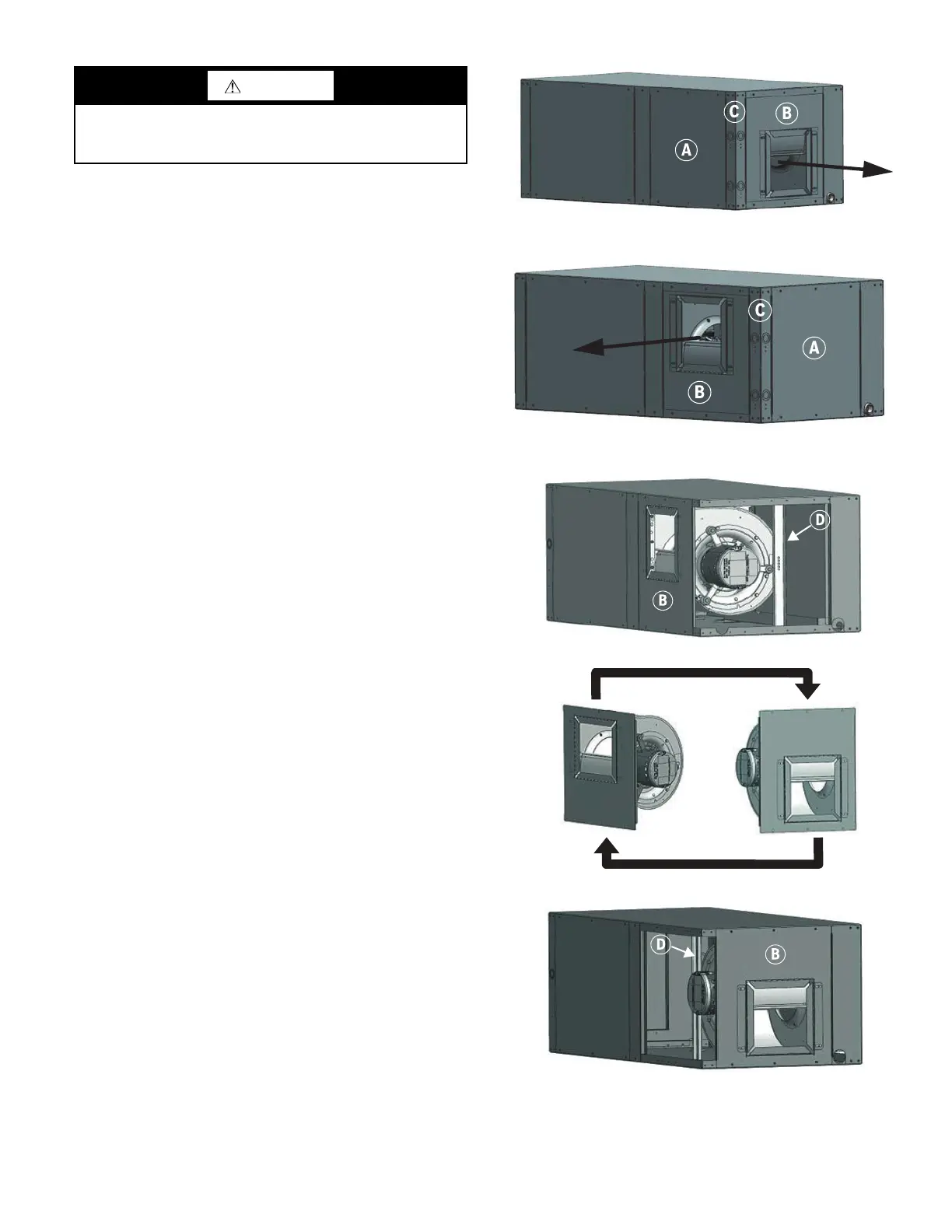
HORIZONTAL SUPPLY AIR CONFIGURATION
CONVERSION
The supply air location can be field converted from end blow
(back discharge) to straight through or vice-versa.
NOTE: Blower configuration changes should be done prior to unit
being installed in the final location.
To convert the supply air direction, follow the steps below
(callouts in Fig. 11-13):
1. If the unit is connected to power, shut Off the unit and discon-
nect switch or circuit breaker.
2. Locate the motor access panel (A). Remove the three screws
at top and the three screws at the bottom of the panel.
Remove the access panel and place it aside.
3. Be careful not to damage the refrigerant coils or any other
internal unit components.
4. Locate blower panel (B). Remove the three screws from top
and the three screws from bottom of the panel. Leave the
blower panel in place on the base pan.
5. Locate access panel corner post (C). Remove the four screws
from top and the four screws from the bottom. Remove the
corner post and set it aside.
6. Locate blower support bracket (D). Remove the one screw
and set it aside.
7. Move blower panel (B) with blower to desired location, rotat-
ing it 180°. (See Fig. 13.) The motor power and control har-
ness can be unplugged to facilitate blower relocation.
8. Reinstall access panel corner post (C) using the eight screws
previously removed.
9. Fasten blower panel (B) using the six screws previously
removed.
10. Reinstall and fasten blower support bracket (D) using the one
screw previously removed.
11. Reattach the motor power and control harness if disconnected
earlier.
12. Reinstall and fasten motor access panel (A) using the six
screws previously removed.
Fig. 11 — End Blow (back discharge) Orientation
Fig. 12 — Straight Through Orientation
Fig. 13 — Blower Configuration
CAUTION
Do not connect discharge ducts directly to the blower outlet.
The factory filter rack should be left in place on a free return
system.
Straight
Through
End
Blow
Bekijk gratis de handleiding van Carrier Aquazone 50WD, stel vragen en lees de antwoorden op veelvoorkomende problemen, of gebruik onze assistent om sneller informatie in de handleiding te vinden of uitleg te krijgen over specifieke functies.
Productinformatie
| Merk | Carrier |
| Model | Aquazone 50WD |
| Categorie | Niet gecategoriseerd |
| Taal | Nederlands |
| Grootte | 15865 MB |


