Carrier Aquazone 50WD handleiding
Handleiding
Je bekijkt pagina 14 van 84
14
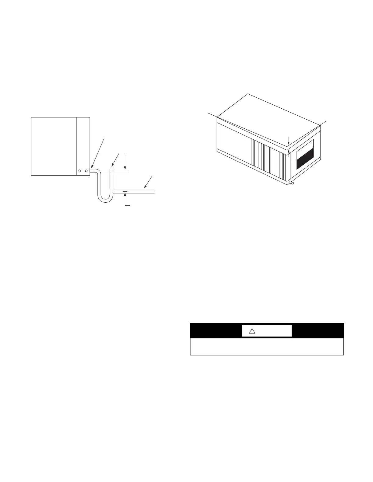
Step 6 — Install Condensate Drain
All units include a condensate drain pan under the evaporator coil.
Units with waterside economizer have an additional condensate
drain pan under the economizer coil.
HORIZONTAL UNITS
A drain line must be connected to each drain pain and pitched
away from the unit a minimum of 1/8 in. per foot to allow the con-
densate to flow away from the unit.
This connection must be in conformance with local plumbing
codes. A trap must be installed in the condensate line to ensure
free condensate flow. (Heat pumps are not internally trapped.) A
vertical air vent is sometimes required to avoid air pockets. See
Fig. 14.
Fig. 14 — Condensate Drain (Horizontal Units)
The depth of the trap depends on the amount of positive or nega-
tive pressure on the drain pan. A second trap must not be included.
The horizontal unit should be pitched approximately 1/4 in. to-
wards the drain in both directions, to facilitate condensate remov-
al. See Fig. 15.
VERTICAL UNITS
Vertical configuration units are internally trapped from the fac-
tory. A second trap must NOT be included.
Step 7 — Pipe Connections
All WSHP units use female pipe thread fittings for water connec-
tions. Refer to Fig. 2 and 3 for connection sizes. When making
piping connections, consider the following:
• Use a backup wrench when making screw connections to
unit to prevent internal damage to piping.
• Insulation may be required on piping to avoid condensa-
tion in the case where fluid in loop piping operates at tem-
peratures below dew point of adjacent air.
• Flexible hoses should be used between the unit and the rig-
id system to avoid possible vibration.
• Supply and return piping must be as large as the unit con-
nections on the heat pump. Never use flexible hoses of a
smaller inside diameter than that of the water connections
on the unit.
• Piping systems that contain steel pipes or fittings may be
subject to galvanic corrosion. Dielectric fittings may be
used to isolate the steel parts of the system to avoid gal-
vanic corrosion.
• Teflon tape thread sealant is recommended when connect-
ing water piping connections to the units to insure against
leaks and possible heat exchanger fouling.
• Balancing valve and supply/return manual isolation valves
must be provided for unit isolation and water flow
balancing.
• Ensure unit receives the appropriate water flow during op-
eration. To verify the correct water flow, utilize pressure/
temperature ports positioned at the supply and return water
lines. Refer to Fig. 43 and 44 for water pressure drop
across water to refrigerant heat exchanger.
• Avoid all plastic to metal threaded fittings due to the po-
tential to leak. Use a flange fitted substitute.
• Route piping to avoid service access areas to unit.
• Flush the piping system prior to operation to remove dirt
and foreign materials from the system.
Fig. 15 — Pitched Unit
WATER QUALITY GUIDELINES
Units are supplied with either a copper or optional cupronickel co-
axial water coil. Copper is adequate for ground water that is not
high in mineral content.
Carrier recommends proper testing to assure the well water quality
is suitable for use with water source equipment. In conditions an-
ticipating moderate scale formation or in brackish water a cupron-
ickel heat exchanger is recommended. Additional considerations:
A secondary heat exchanger (plate frame between the unit and the
open cooling tower or open loop ground water system) may also
be used. It is imperative that all air is eliminated from the closed
loop side of the heat exchanger to prevent condenser fouling.
In all applications, the quality of the water circulated through the
heat exchanger must fall within the ranges listed in Table 3, Water
Quality Guidelines. Consult a local water treatment firm, indepen-
dent testing facility, or local water authority for specific recom-
mendations to maintain water quality within the published limits.
Condensate Drain
Connection
Vent (optional)
Slope Down
Min. 1/8"
Per Foot
Trap Down
2" Min.
CAUTION
Water piping exposed to extreme, low ambient temperatures is
subject to freezing.
Elevation Line
When Mounted Level
1/4"
[13]
NOTE: Dimensions in [ ]
are millimeters.
Bekijk gratis de handleiding van Carrier Aquazone 50WD, stel vragen en lees de antwoorden op veelvoorkomende problemen, of gebruik onze assistent om sneller informatie in de handleiding te vinden of uitleg te krijgen over specifieke functies.
Productinformatie
| Merk | Carrier |
| Model | Aquazone 50WD |
| Categorie | Niet gecategoriseerd |
| Taal | Nederlands |
| Grootte | 15865 MB |


