Carrier Aquazone 50WD handleiding
Handleiding
Je bekijkt pagina 12 van 84
12
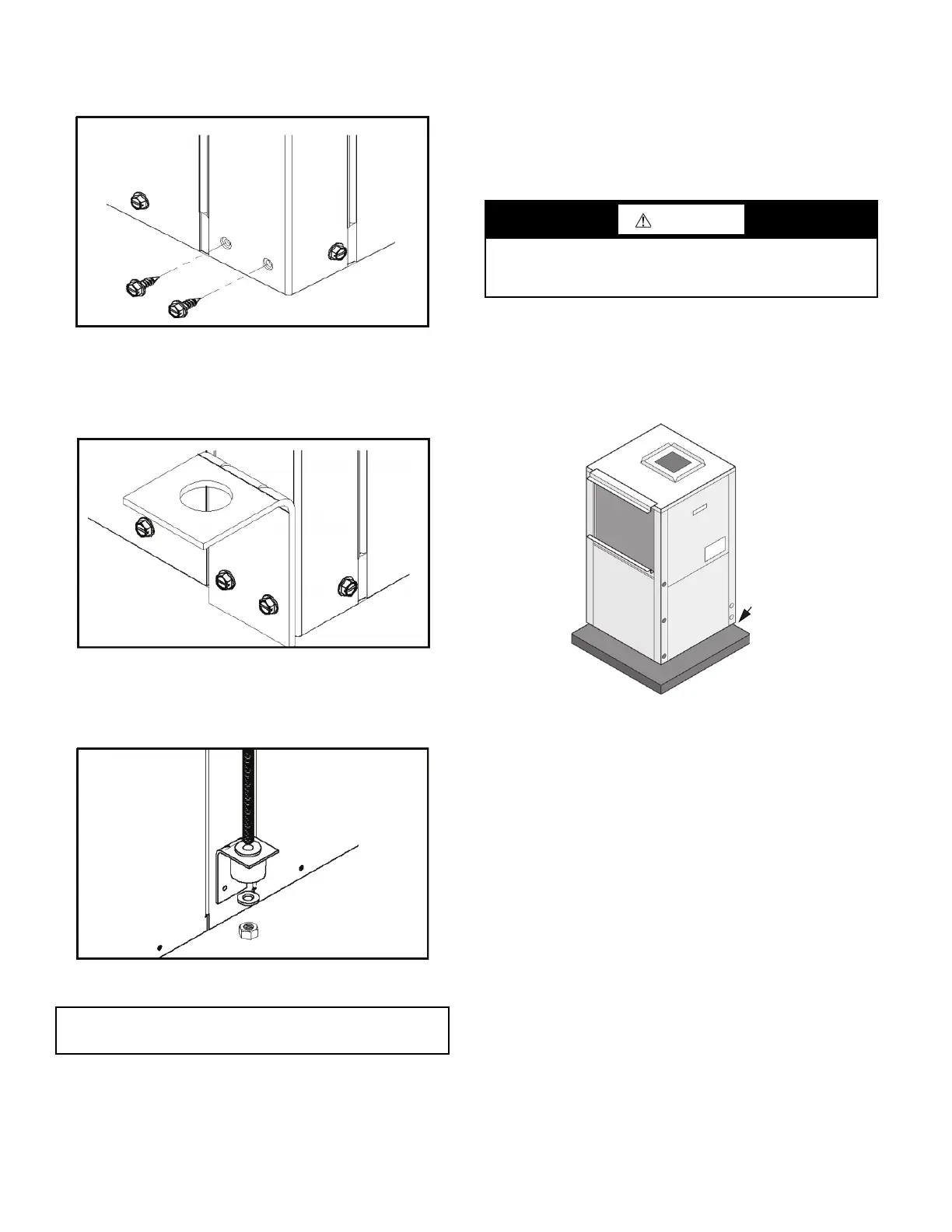
Hanging Bracket Installation
1. Remove and discard factory-provided screws from location
where hanging brackets will be installed. (see Fig. 7).
Fig. 7 — Removing Factory Screws
2. Mount 4 brackets to unit corner post using the bolts provided
in the kit, as shown in Fig. 8. DO NOT re-use the screws
removed from the unit during Step 1 to mount the hanging
brackets on the unit.
Fig. 8 — Mounting Brackets
3. Install rubber grommet on the bracket as shown in Fig. 9.
4. Hang the unit and assemble the field-provided threaded rod,
nuts, and washers on the brackets as shown in Fig. 9.
Fig. 9 — Hanging the Unit
Horizontal units installed above the ceiling must conform to all
local codes. An auxiliary drain pan, if required by code, should be
at least 4 in. larger than the bottom of the heat pump.
Plumbing connected to the heat pump must not come in direct
contact with joists, trusses, walls, etc. Some applications require
an attic floor installation of the horizontal unit. In this case the unit
should be set in a full size secondary drain pan on top of a vibra-
tion absorbing mesh.
The secondary drain pan prevents possible condensate overflow or
water leakage damage to the ceiling. The secondary drain pan is
usually placed on a plywood base isolated from the ceiling joists
by additional layers of vibration absorbing mesh. In both cases, a
3/4 in. drain connected to this secondary pan should be run to an
eave at a location that will be noticeable.
VERTICAL UNITS
Vertical units should be mounted level on a vibration absorbing
pad slightly larger than the unit base in order to minimize vibration
transmission from the unit to the building structure (see Fig. 10). It
is generally not necessary to anchor the unit unless required by lo-
cal code.
Fig. 10 — Mounting Vertical Units
All major service access for the vertical models is from the front
side of the unit. When installing the unit in a confined space such
as a closet, ensure the service panel screws are accessible, that
the filter can be replaced without damage and that water and
electrical connections are accessible. For models with a unit-
mounted disconnect switch, make sure the switch can be easily
seen and operated.
To reduce sound transmission, units should be installed using
flexible electrical conduit and hose kits. Care should be taken to
ensure that no part of the unit cabinet is touching part of the
building structure. For ducted return applications, a flexible duct
connection should be used. Mount the unit on a vibration
absorption pad slightly larger than the entire base to minimize vi-
bration transmission. It is not necessary to mount the unit on the
floor.
Step 5 — Check Duct System
All units are provided with a return air duct flange and supply
air duct connections. Refer to unit dimensional drawings
(Fig. 2 and 3) for physical dimensions of the collar and flange.
A flexible connector is recommended for supply and return air
duct connections on metal duct systems. All metal ducting
should be insulated with a minimum of 1 in. duct insulation to
avoid heat loss or gain and prevent condensate from forming
during the cooling operation. Application of the unit to uninsu-
lated ductwork is not recommended as the unit’s performance
will be adversely affected.
IMPORTANT: Units larger than six tons include an integral
angle iron frame with mounting holes present.
CAUTION
If the unit is located in a crawl space, the bottom of the unit
must be at least 4-in. above grade to prevent flooding of the
electrical parts due to heavy rains.
Vibration
Mounting
Pad
Bekijk gratis de handleiding van Carrier Aquazone 50WD, stel vragen en lees de antwoorden op veelvoorkomende problemen, of gebruik onze assistent om sneller informatie in de handleiding te vinden of uitleg te krijgen over specifieke functies.
Productinformatie
| Merk | Carrier |
| Model | Aquazone 50WD |
| Categorie | Niet gecategoriseerd |
| Taal | Nederlands |
| Grootte | 15865 MB |


