Carrier WeatherMaker 48GE handleiding
Handleiding
Je bekijkt pagina 32 van 80
32
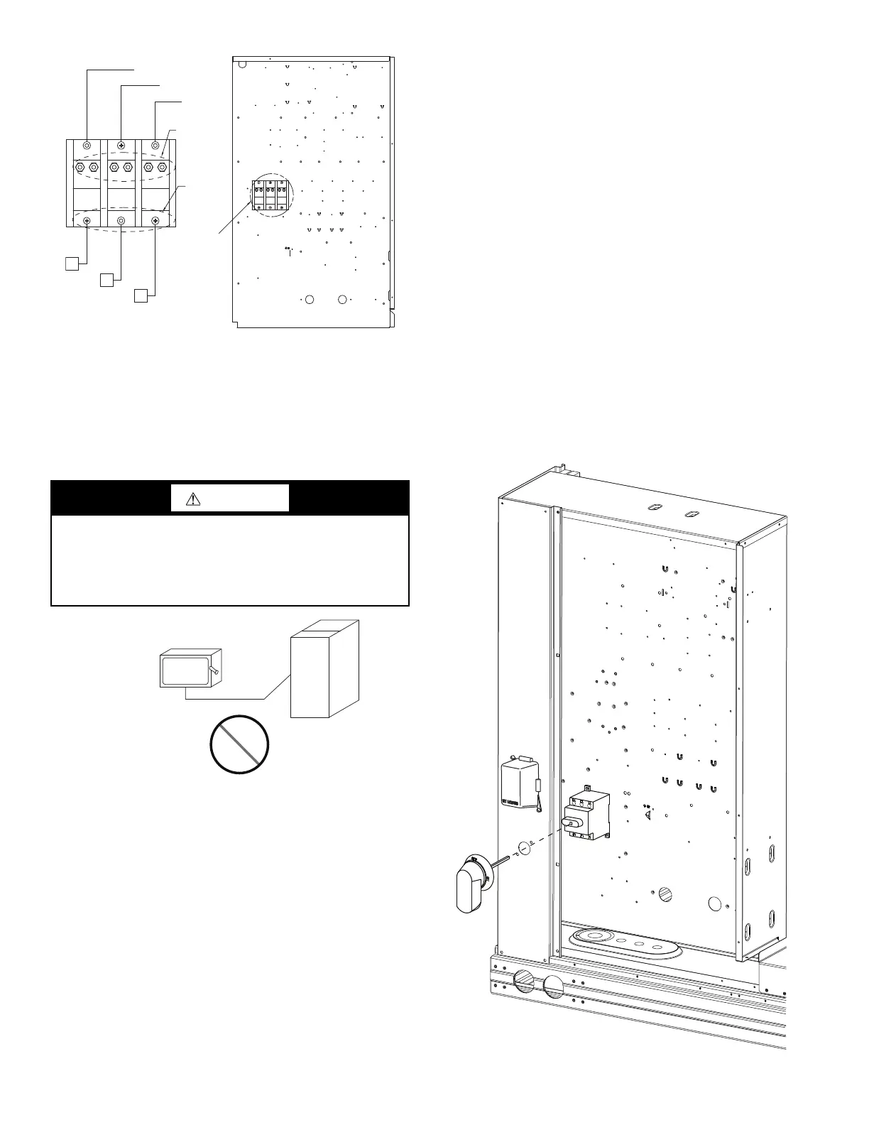
Fig. 44 — Location of TB1
Field power wires are connected to the unit at line-side pressure
lugs on the terminal block (see wiring diagram label for control
box component arrangement) or at factory-installed option non-
fused disconnect switch. Use copper conductors only. See Fig. 45.
NOTE: Make field power connections directly to line connection
pressure lugs only.
Fig. 45 — Disconnect Switch and Unit
UNITS WITHOUT FACTORY-INSTALLED NON-FUSED
DISCONNECT OR HACR
When installing units, provide a disconnect switch of adequate
size per NEC (National Electrical Code). Disconnect sizing data is
provided on the unit informative plate. Locate on unit cabinet or
within sight of the unit per national or local codes. Do not cover
unit informative plate if mounting the disconnect on the unit
cabinet.
UNITS WITH FACTORY-INSTALLED NON-FUSED
DISCONNECT OR HACR
The factory-installed option non-fused disconnect switch (NFD)
or HACR is located in the main control box. The manual switch
handle and shaft are shipped in the control box and must be
mounted on the corner post adjacent to the control box (see Fig. 46
or 47). Note that the tape covering the hole for the shaft in the cor-
ner post must be removed prior to handle and shaft installation.
To field install the NFD shaft and handle:
1. Open the control box panel.
2. Make sure the NFD shipped from the factory is at OFF posi-
tion (the arrow on the black handle knob or on the silver
metal collar is at OFF).
3. Insert the shaft with the cross pin on the top of the shaft in the
horizontal position.
4. Measure the tip of the shaft to the outside surface of the cor-
ner post to be 0.88 inches.
5. Tighten the locking screw to secure the shaft to the NFD.
6. Turn the handle to the OFF position with red arrow pointing
at OFF.
7. Install the handle on to the corner post vertically with the red
arrow pointing up.
8. Secure the handle to the corner post with (2) screws and lock
washers supplied.
Fig. 46 — Handle and Shaft Assembly for NFD
WARNING
FIRE HAZARD
Failure to follow this warning could result in personal injury,
death, or property damage.
Do not connect aluminum wire between disconnect switch and
unit. Use only copper wire.
Load
Side
See
Detail A
Detail A
Line
Side
BLK
YEL
BLU
Control Box
L3
L2
L1
Copper
Wire Only
Electric
Disconnect
Switch
Aluminum
Wire
Bekijk gratis de handleiding van Carrier WeatherMaker 48GE, stel vragen en lees de antwoorden op veelvoorkomende problemen, of gebruik onze assistent om sneller informatie in de handleiding te vinden of uitleg te krijgen over specifieke functies.
Productinformatie
| Merk | Carrier |
| Model | WeatherMaker 48GE |
| Categorie | Niet gecategoriseerd |
| Taal | Nederlands |
| Grootte | 10499 MB |


