Carrier WeatherMaker 48GE handleiding
Handleiding
Je bekijkt pagina 31 van 80
31
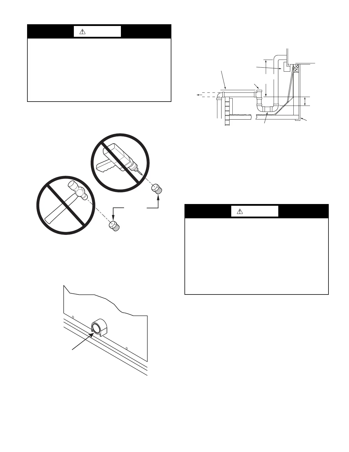
If orifice hole appears damaged or it is suspected to have been re-
drilled, check orifice hole with a numbered drill bit of correct size.
Never re-drill an orifice. A burr-free and squarely aligned orifice
hole is essential for proper flame characteristics. See Fig. 41.
Fig. 41 — Orifice Hole
Step 12 — Install External Condensate Trap and
Line
The unit has one 3/4 in. condensate drain connection on the end of
the condensate pan (see Fig. 42). See Fig. 4, 9, and 14 for the loca-
tion of the condensate drain connection.
Fig. 42 — Condensate Drain Pan Connection
The piping for the condensate drain and external trap can be com-
pleted after the unit is in place. Hand tighten fittings to the drain
pan fitting. Provide adequate support for the drain line. Failure to
do so can result in damage to the drain pan. See Fig. 43.
Fig. 43 — Condensate Drain Piping Details
All units must have an external trap for condensate drainage. In-
stall a trap at least 4 in. (102 mm) deep and protect against freeze-
up. If drain line is installed downstream from the external trap,
pitch the line away from the unit at 1 in. per 10 ft (25 mm in 3 m)
of run. Do not use a pipe size smaller than the unit connection
(3/4 in.).
Step 13 — Make Electrical Connections
NOTE: Field-supplied wiring shall conform with the limitations
of minimum 63°F (3°C) rise.
FIELD POWER SUPPLY
If equipped with optional powered convenience outlet: the power
source leads to the convenience outlet’s transformer primary are
not factory connected. Installer must connect these leads accord-
ing to required operation of the convenience outlet. If an always-
energized convenience outlet operation is desired, connect the
source leads to the line side of the unit-mounted disconnect.
(Check with local codes to ensure this method is acceptable in
your area.) If a de-energize via unit disconnect switch operation of
the convenience outlet is desired, connect the source leads to the
load side of the unit disconnect. On a unit without a unit-mounted
disconnect connect the source leads to the terminal block with unit
field power leads. See Fig. 44.
WARNING
Failure to follow this warning could result in personal injury,
death and/or property damage.
• Connect gas pipe to unit using a backup wrench to
avoid damaging gas controls.
• Never purge a gas line into a combustion chamber.
• Never test for gas leaks with an open flame. Use a
commercially available soap solution made specifically
for the detection of leaks to check all connections.
• Use proper length of pipe to avoid stress on gas control
manifold.
Burner
Orifice
Condensate
Drain
Connection
WARNING
Failure to follow this warning could result in personal injury or
death.
Do not use gas piping as an electrical ground.
Unit cabinet must have an uninterrupted, unbroken electrical
ground to minimize the possibility of personal injury if an
electrical fault should occur. This ground may consist of
electrical wire connected to unit ground lug in control
compartment, or conduit approved for electrical ground when
installed in accordance with NEC (National Electrical Code);
ANSI/NFPA 70, latest edition (in Canada, Canadian Electrical
Code CSA [Canadian Standards Association] C22.1), and
local electrical codes.
Minimum Pitch
1 in. (25 mm) Per
10 ft (3 m) of Line
To Roof
Drain
Base Rail
Open
Vent
3 in. (76 mm)
See Note
Roof
Curb
Drain Plug
NOTE: Trap should be deep enough to offset maximum unit static
difference. A 4 in. (102 mm) trap is recommended.
Min
Bekijk gratis de handleiding van Carrier WeatherMaker 48GE, stel vragen en lees de antwoorden op veelvoorkomende problemen, of gebruik onze assistent om sneller informatie in de handleiding te vinden of uitleg te krijgen over specifieke functies.
Productinformatie
| Merk | Carrier |
| Model | WeatherMaker 48GE |
| Categorie | Niet gecategoriseerd |
| Taal | Nederlands |
| Grootte | 10499 MB |


