Carrier WeatherMaker 48GE handleiding
Handleiding
Je bekijkt pagina 33 van 80
33
To field install the HACR shaft and handle:
1. Open the control box panel.
2. Make sure the HACR shipped from the factory is at OFF
position (the white arrow pointing at OFF).
3. Insert the shaft all the way with the cross pin on the top of the
shaft in the horizontal position.
4. Measure the tip of the shaft to the outside surface of the cor-
ner post to be 0.88 inches.
5. Tighten the locking screw to secure the shaft to the HACR.
6. Turn the handle to the OFF position with red arrow pointing
at OFF.
7. Install the handle on to the corner post vertically with the red
arrow pointing up.
8. Secure the handle to the corner post with (2) screws and lock
washers supplied.
Fig. 47 — Handle and Shaft Assembly for HACR
ALL UNITS
All field wiring must comply with NEC and all local
requirements.
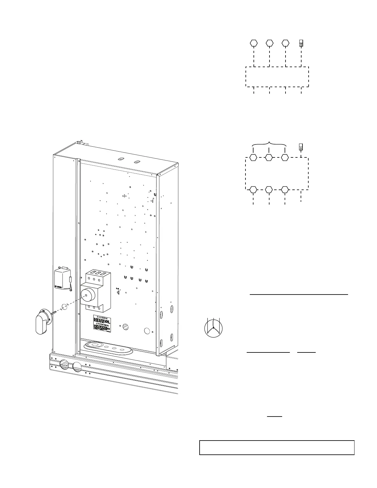
Size wire based on MCA (Minimum Circuit Amps) on the unit in-
formative plate. See Fig. 48 for power wiring connections to the
unit power terminal blocks and equipment ground. Maximum
wire size is 2/0 AWG per pole.
Fig. 48 — Power Wiring Connections
Provide a ground-fault and short-circuit over-current protection
device (fuse or breaker) per NEC Article 440 (or local codes).
Refer to unit informative data plate for MOCP (Maximum Over-
current Protection) device size.
Voltage to compressor terminals during operation must be within
voltage range indicated on unit nameplate. On 3-phase units, volt-
ages between phases must be balanced within 2% and the current
within 10%. Use the following formula to determine the percent
of voltage imbalance.
Example: Supply voltage is 230-3-60
Determine maximum deviation from average voltage.
(AB) 227-224 = 3-v
(BC) 231-227 = 4-v
(AC) 227-226 = 1-v
Maximum deviation is 4-v.
Determine percent of voltage imbalance.
This amount of phase imbalance is satisfactory as it is below the maximum
allowable 2%.
% Voltage
Imbalance
= 100 x
max voltage deviation from average voltage
average voltage
AB = 224-v
BC = 231-v
AC = 226-v
Average Voltage =
(224 + 231 + 226)
=
681
= 227
33
% Voltage Imbalance = 100x
4
= 1.76%
227
IMPORTANT: If the supply voltage phase imbalance is more than 2%, contact
your local electric utility company immediately.
11 13
L1
L2 L3 Ground
(GR)
TB1
208/230-3-60
460-3-60
575-3-60
T1 T2 T3
L1 L2 L3
L1 L2 L3
Factory
Wiring
Disconnect
per NEC
Optional
Disconnect
Switch
or HACR
12
Equip
GR Lug
Ground
(GR)
Equip
GR Lug
Units Without Disconnect or HACR Option
Units With Disconnect or HACR Option
A
B
C
MOTOR
Bekijk gratis de handleiding van Carrier WeatherMaker 48GE, stel vragen en lees de antwoorden op veelvoorkomende problemen, of gebruik onze assistent om sneller informatie in de handleiding te vinden of uitleg te krijgen over specifieke functies.
Productinformatie
| Merk | Carrier |
| Model | WeatherMaker 48GE |
| Categorie | Niet gecategoriseerd |
| Taal | Nederlands |
| Grootte | 10499 MB |


