Carrier Aquazone 50WD handleiding
Handleiding
Je bekijkt pagina 45 van 84
45
PRE-START-UP
System Checkout
After completing the installation, and before energizing the unit,
the following system checks should be made prior to initial
startup:
1. Verify the supply voltage to the heat pump is in accordance
with the nameplate ratings.
2. Verify the control transformer is set to the correct voltage for
208/230-v units (factory setting is 230-v).
3. Make sure that all electrical connections are tight and secure.
4. Check the electrical fusing/breaker and wiring for the correct
size.
5. Verify the low voltage wiring between the thermostat or DDC
controls and the unit is correct.
6. Verify the water piping is complete and correct.
7. Verify there are no leaks in the external piping or in the inter-
nal unit piping. Correct as necessary.
8. Verify the isolation or flow control valves are open and that
any automatic flow control valve or balancing valve are set to
the correct setting.
9. Check the water flow is correct and adjust if necessary.
10. Check the blower for free rotation, and that it is secured to the
shaft.
11. Verify the foam blower shipping support has been removed.
12. Vertical Units Only - Verify vibration isolation has been
provided and that the unit has been installed on a solid
structure.
13. Horizontal Units Only - Verify the hanging brackets have
been installed and that the unit is secured to an adequate
support structure.
14. Verify the unit has proper service clearance. Be certain that all
access panels are secured in place.
15. Verify ductwork has been properly fastened to supply and
return duct collars.
16. Verify the ductwork is free from obstruction and that all
dampers or registers are open.
17. Make sure return air filters are positioned correctly in the
filter rack if removed during installation.
18. Verify the unit is not in TEST mode.
19. Verify all control components have been properly configured
and that all control components have been wired.
20. For units with TruVu DDC controller, verify a space tempera-
ture input is provided via ZS sensor, or non-communication
zone sensor (10K thermistor), or over the network and that a
commissioning interface is available.
CLEAN AIR COIL
To obtain maximum performance, clean the air coil before starting
the unit. A ten percent solution of dishwasher detergent and water
is recommended for both sides of the coil. Rinse thoroughly with
water.
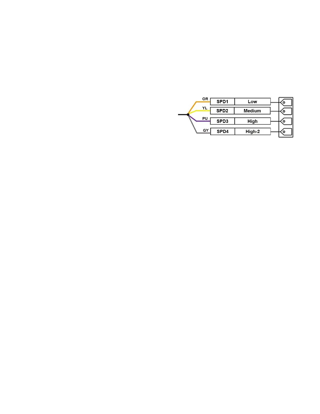
Set Blower Motor Speed
CONSTANT TORQUE (ECM) MOTOR
50WD unit sizes 007-012 in 208/230-v, or 265-v are available
with constant torque ECM blower motors, and have 4-speed
settings.
Speed Tap 1: Fan Only operation
Speed Tap 2: Passive Dehumidification
Speed Tap 3: Full Load
Speed Tap 4: Extra speed tap. Not connected from factory.
See Tables 15-16 for blower performance by speed setting, and for
the factory default motor setting.If a motor speed change is re-
quired, follow the instructions below:
1. Disconnect power to the heat pump and follow all proper
lockout and tagout procedures to ensure that power is
removed from the unit.
2. Remove the blower access panel and access the torque tap
wire on the motor.
3. Change the torque tap wire to on the molex plug to one of the
four speed settings. See Fig. 42.
Fig. 42 — 4-Speed Settings Constant Torque ECM
Pin Diagram
NOTE: Refer to the blower performance table to see available
speed taps.
NOTE: Constant Torque Motors (ECM) are programmed to have
a 30s ramp up/down. Contact application engineering for details
on applications where immediate ramp down is required.
CONSTANT AIRFLOW (ECM) MOTOR
The 50WD units in 208/230-v, 265-v, or 460-v are available with a
constant airflow ECM blower motor. These motors dynamically
adjust their power output to precisely match the desired airflow on
a pre-programed fan curve. See Tables 17-18 for blower perfor-
mance by speed setting, and for the factory default motor setting.
These motors include the following features:
1. Three Speed Settings: Units are factory set to “NORM” but
can be field adjusted to “+” to increase CFM by 15% or to “-”
to reduce CFM by 15%. See the constant airflow ECM motor
blower performance table for complete details on available
CFM for each unit size (refer to the Wire Control Connec-
tions section of this manual).
2. Low CFM Ventilation: Units circulate air at 70% of full
airflow rate when there is a call for fan only.
3. Passive Dehumidification: Reduces airflow during a cooling
call when dehumidification is also required. This reduces the
sensible heat ratio of the cooling coil and extends cooling run
time to dehumidify more effectively (refer to the Wire
Control Connections section of this manual).
4. Test Mode: Operates the motor at a 70% torque setting. This
setting can be used to diagnose programming problems in the
motor itself (refer to the Wire Control Connections section of
this manual).
5. CFM Indicator Light: indicator light blinks for each 100
CFM of air delivered.
NOTE: This blink code is approximate and should not replace test
and balance.
Bekijk gratis de handleiding van Carrier Aquazone 50WD, stel vragen en lees de antwoorden op veelvoorkomende problemen, of gebruik onze assistent om sneller informatie in de handleiding te vinden of uitleg te krijgen over specifieke functies.
Productinformatie
| Merk | Carrier |
| Model | Aquazone 50WD |
| Categorie | Niet gecategoriseerd |
| Taal | Nederlands |
| Grootte | 15865 MB |


