Carrier 39S handleiding
Handleiding
Je bekijkt pagina 51 van 64
51
VFD
Factory installed variable frequency drives (VFD) are wired to the
motor and fully tested before shipment. Drive programming is
also done at the factory.
Open the VFD front cover and the fan section access door to
check for any damage before proceeding.
39SHK and 39SHF products have several control options. For all
options, the VFD can be put into manual mode from the keypad.
Other control options allow for field-supplied fan speed signal and
for keypad control (manual speed setting). VFDs are located
inside the blower compartment. Keypad is mounted on unit exteri-
or for all control options.
Typical wiring diagrams are shown FOR REFERENCE, see
Fig. 71-73. Always refer to the wiring diagram on the air handling
unit for actual wiring.
Connect electrical service to unit. Refer to unit wiring diagram.
NOTE: Check motor rating plate for correct line voltage.
For power supply connection, route field power wiring to field-
provided and installed disconnect switch and from switch to junc-
tion box on unit. Unit is internally wired from junction box to
VFD.
Refer to nameplate full load amps (FLA), maximum overcurrent
protection device (MOPD) and minimum circuit ampacity
(MCA). Also refer to wiring diagram affixed to unit to make con-
trol and power wiring connections.
NOTE: Installer is responsible for power wiring and branch circuit
over current protection.
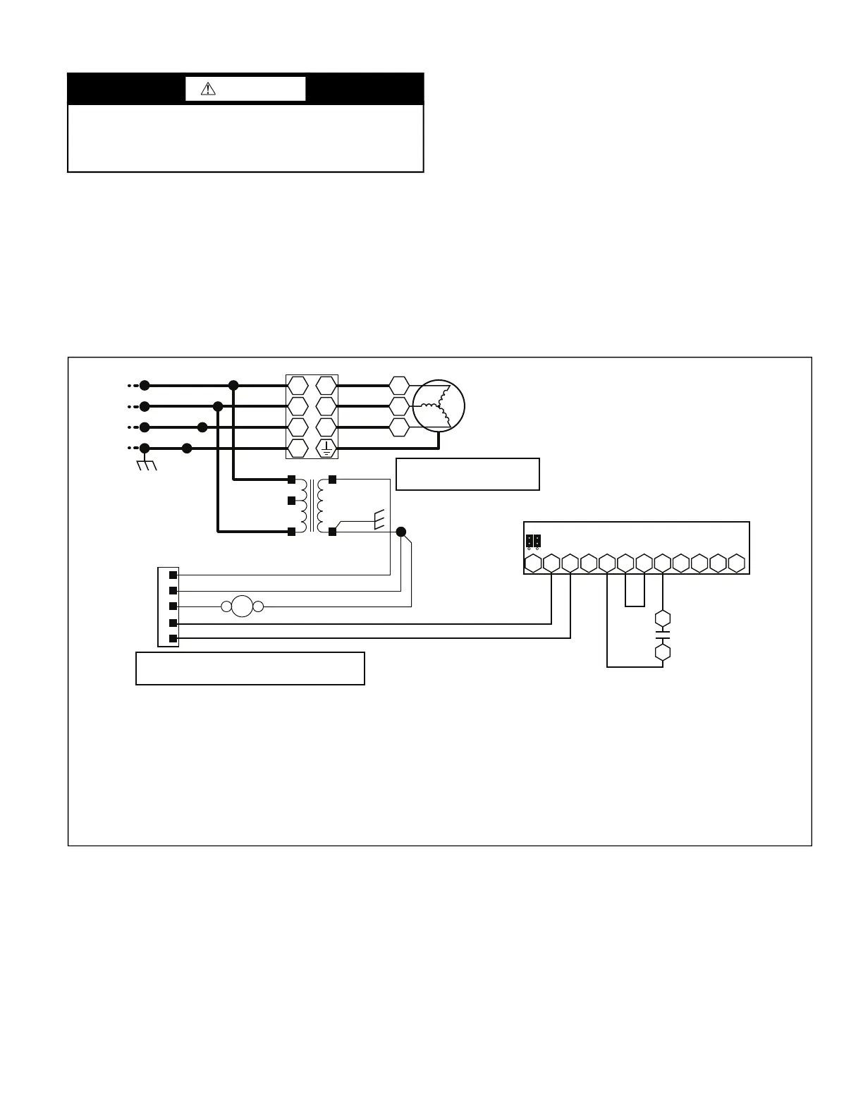
Fig. 71 — Control Option “A,” 4-20 mA Fan Speed Control Typical Wiring Diagram
WARNING
Dangerous voltage is present when input power is connected.
After disconnecting power supply wait at least 5 minutes be-
fore performing any maintenance. Failure to follow these in-
structions may result in personal injury or equipment damage.
U1 U2
V1 V2
W1 W2
PE
VFD
BLK/134
YEL/135
BLU/136
GRN/137
BLK/140
RED/141
ORN/142
GRN/143
1
3
2
IFM
BLK/150
RED/151
ORN/152
GRN/153
L1
L2
L3
208/240v – 3Ø
GND
USE COPPER
SUPPLY WIRES.
BLK/101
240V
208V
YEL/102
COM
TRAN 1
RED/505
R
C
G
TB1
RED/505
BRN/502
BLK/504
ABFR1
BRN/503
GRN/500
BRN/501
24 VAC
TRAN 1 IS FACTORY WIRED FOR 230V.
MOVE WIRE BLK/101 TO THE 208V
TAP FOR 208V APPLICATIONS.
AI1
AI2
S1
VFD
BLU/508
VIO/506
BLU/507
4
7
BLK/510
YEL/509
+
–
YEL/509
BLK/510
1
2
3
4
9
10
11
12
13
14
15
16
VFD IS FACTORY CONFIGURED FOR 4-20mA OPERATION. IN THE
FIELD, MOVE THE S1 JUMPER TO “V” FOR 0-10 VDC OPERATION
AND CHANGE PARAMETER 1301 TO ZERO
NOTES:
1. This diagram represents the factory-installed electrical option with 4-20 mA field signal input for fan speed control. Includes VFD keypad
mounted on outside of unit.
2. Typical wiring is shown. For exact wiring, refer to the wiring diagram provided with the unit.
3. Field wiring includes power wiring (upper left hand corner) and low voltage control wiring (terminal block TB1).
4. Units ordered for 208V-240V voltage selection are factory wired for 240V. Field may rewire motor and transformer primary tap for operation
at 208V.
5. Selection of field provided and installed electrical components is the responsibility of the installer, including branch circuit protection and
wiring.
6. To start the fan, connect R and G to energize fan relay FR1. Control fan speed by providing 4-20 mA signal at + and - connections at TB1.
7. The control power (R and C at terminal block TB1) can be used to power a standard 24VAC thermostat, DX relay and up to 2 control valves.
Bekijk gratis de handleiding van Carrier 39S, stel vragen en lees de antwoorden op veelvoorkomende problemen, of gebruik onze assistent om sneller informatie in de handleiding te vinden of uitleg te krijgen over specifieke functies.
Productinformatie
| Merk | Carrier |
| Model | 39S |
| Categorie | Niet gecategoriseerd |
| Taal | Nederlands |
| Grootte | 10967 MB |


