Carrier 39S handleiding
Handleiding
Je bekijkt pagina 42 van 64
42
In the first example we will determine the tons per circuit when
both TXVs are active and the compressor is unloaded to its mini-
mum of 33%.
= .55 tons per circuit at minimum unloading UNACCEPTABLE
If we install a liquid line solenoid valve before one of the TXVs
and close it so that only one TXV is active when the compressor is
unloaded to its minimum of 33%, we see the following:
= 1.10 tons per circuit at minimum unloading ACCEPTABLE
There are three different options to control tons per circuit when
using an unloading compressor. The first is to use drop solenoid
valve control as illustrated above and let the suction cutoff unload-
ers “ride” with the load. The second is to use drop solenoid valve
control as illustrated above with electric unloaders and let the con-
trol algorithm determine the combination of solenoid valves and
unloaders to limit tons per circuit to acceptable limits. The third is
to limit the minimum amount of unloading so that tons per circuit
is within acceptable limits.
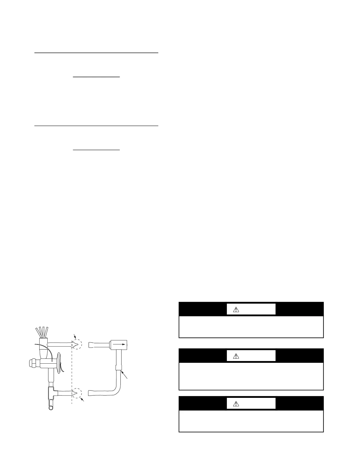
Heat Pump Bypass Kit
The Heat Pump Bypass Kit can be used with 39SHK, 39SM,
39SR, and 39SV07-09 units. Follow this procedure to install the
kit:
1. Cut off the ends of the stubout tubes near the location of the
dotted lines shown in Fig. 58.
2. Slip the swaged ends of the bypass kit over the open tube
ends.
3. Cut copper ell as required for fit.
4. Check assembly to ensure proper orientation for free flow.
5. Braze the joints. The check valve body must be protected
from overheating.
6. Check for leaks.
Fig. 58 — Heat Pump Bypass Kit Installation
Drain Pan Replacement
The following drain pan replacement procedure applies to
39SHC/SHF/SHK units with any standard drain pan offering.
1. Identify drain pan type (plastic or stainless steel).
2. Remove coil stubout panel on the connection side of the unit
(39SHC/SHF/SHK sizes 00-05). For sizes 07-17 skip to
Step 3 (coil panel will be one piece).
3. Remove filter access panel and filter.
4. Remove coil retaining screws (sizes 00-05 have 4 each and
sizes 07-17 contain up to 6 each). Screws are accessible from
the filter side of the unit. Screws are used to attach the first
coil to the coil panel.
5. Remove top panel screws at sides and rear (do not remove
front screws).
NOTE: Ensure unit is properly supported before removing screws.
Top panel will not be removed.
6. Remove screws at bottom of coil panel. Remove coil
panel.
7. Next, remove the coils from the unit along with the drain pan.
NOTE: Drain pan will slide out of the unit.
NOTE: To remove coils, lift top panel.
8. If the unit is single wall construction, simply install the new
drain pan and the coils.
9. For double wall units, coil panels have a liner panel that ends
above the edge of the drain pan. For these panels, apply adhe-
sive backed closed cell insulation (15-1/4 in. x 1-1/2 in.) to
the inside of the coil panel, flush with the bottom of the liner
panel. This provides an air seal to the end of the drain pan.
Proceed with the installation of the new drain pan and coils.
10. Set coil panel in place and attach coils to the panels. Install
coil panel screws at bottom and top of unit. Install all top
panel screws.
NOTE: Ensure that the top filter rail is behind the top panel
flange, and that the rear leg is on the outside of the top panel
flange.
NOTE: Galvanized drain pans shall be attached to coil panel
using (2) No. 8 sheet metal screws.
11. Reinstall the coil stubout panel (unit sizes 00-05) along with
the filter and filter door.
Coil Removal
=
(1.68 Tons per Circuit) x (33% Minimum Unloading)
x (2 TXVs)
2 TXVs Active
=
(1.68) x (.33) x (2)
2
=
(1.68 Tons per Circuit) x (33% Minimum Unloading)
x (2 TXVs)
1 TXV Active
=
(1.68) x (.33) x (2)
1
CUT
CUT
FREE FLOW
DIRECTION
FIELD BRAZE
AFTER
SIZING
CHECK VALVE
BYPASS ASSEMBLY
a39-4498
WARNING
Never enter an enclosed fan cabinet or reach into a unit while
the fan is running. Failure to follow this warning can result in
severe personal injury.
WARNING
To avoid possible injury or death due to electrical shock, lock
open and tag the fan motor power disconnect switch before
working on a fan. Remove and retain fuses and note removal
on tag.
WARNING
To avoid possible injury or death due to electrical shock, lock
open and tag the electric heat coil power disconnect switch be-
fore working on or near heaters.
Bekijk gratis de handleiding van Carrier 39S, stel vragen en lees de antwoorden op veelvoorkomende problemen, of gebruik onze assistent om sneller informatie in de handleiding te vinden of uitleg te krijgen over specifieke functies.
Productinformatie
| Merk | Carrier |
| Model | 39S |
| Categorie | Niet gecategoriseerd |
| Taal | Nederlands |
| Grootte | 10967 MB |


