Carrier 39S handleiding
Handleiding
Je bekijkt pagina 41 van 64
41
IDT Steam Coil Installation
Refer to drawings to position the coils properly with regard to the
location of the supply and return connections. Ensure that the IDT
coil is pitched with the tubes draining toward the header. The
AHUs provide proper coil pitch when the AHU is installed level.
Refer to schematic piping diagrams and piping connection notes
for the recommended piping methods.
Refrigerant Piping, Direct-Expansion (DX) Coils
Direct-expansion coils are divided into 1 or 2 splits depending
upon the unit size and coil circuiting. Each split requires its own
distributor nozzle, expansion valve, and suction piping. Suction
connections are on the air entering side when the coil is properly
installed. Matching distributor connections for each coil split are
on the air leaving side. See unit label or certified drawing to assure
connection to matching suction and liquid connections.
The lower split of face split coils should be first on, last off.
Row split coils utilize special intertwined circuits; either split of
these row split coils can be first on, last off.
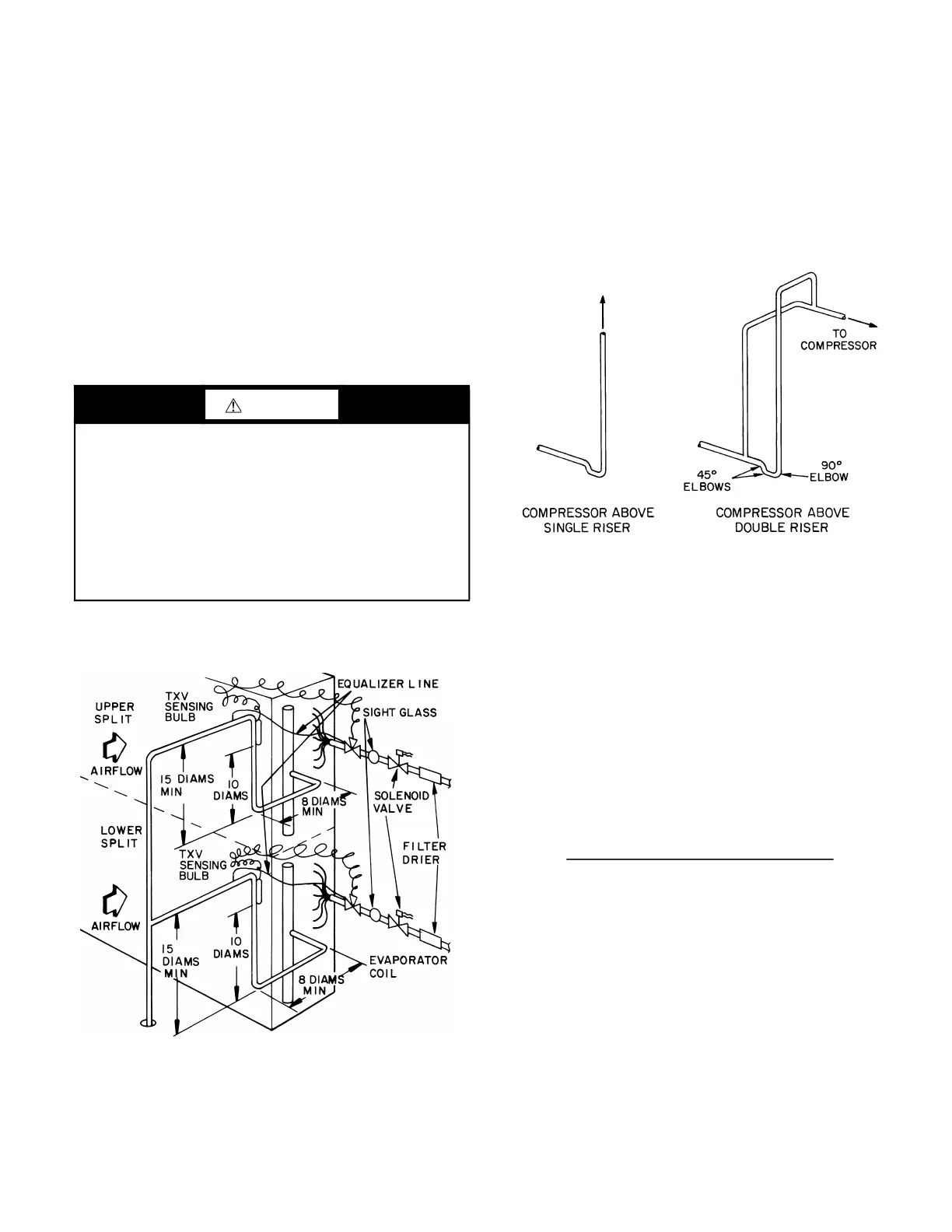
SUCTION PIPING
Connect suction piping as shown in Fig. 56 for face split coil.
Fig. 56 — Face Split Coil Suction Line Piping
Suction line from coil connection to end of the 15-diameter-long
riser should be same tube size as coil connection to ensure proper
refrigerant velocity.
Refer to Carrier System Design Manual, Part 3, and size remain-
ing suction line to compressor for a pressure drop equivalent to
2.0°F. This will provide a total suction line header pressure drop
equivalent to approximately 2.5°F. Refer to Fig. 57 for piping ris-
ers to the compressor.
To minimize the possibility of flooded starts and compressor dam-
age during prolonged light load operation, install an accumulator
in the suction line or a solenoid in the liquid line of last-on, first off
split in row-split applications.
Fig. 57 — Suction Line Riser Piping
EXPANSION VALVE PIPING
Distributor nozzles and expansion valves sized for acceptable per-
formance for a range of conditions are factory supplied. Use the
AHU (air-handling unit) selection program in the electronic cata-
log to select optimal nozzle sizes.
Circuiting selection should result in a circuit loading of 0.8 to
2.0 tons per circuit at design load. Circuit loading must be evaluat-
ed at minimum load to ensure that it does not drop below 0.6 tons
per circuit. Solenoid valves may be used, if necessary, to shut off
the refrigerant supply to individual expansion valves to maintain
adequate coil circuit loading.
Compressor minimum unloading and TXV quantity is necessary
to determine minimum tonnage per circuit.
Minimum Unloading Equation:
Example:
Condensing Unit: 38ARS012
Minimum Unloading: 33%
Coil: 6 row, 11 FPI, Half Circuit
Coil Tons per Circuit: 1.68
Total TXVs: 2
CAUTION
Direct-expansion coils are shipped pressurized with dry nitro-
gen. Release pressure from each coil split through valves in
protective caps before removing caps.
Do not leave piping open to the atmosphere unnecessarily. Wa-
ter and water vapor are detrimental to the refrigerant system.
Until the piping is complete, recap the system and charge with
nitrogen at the end of each workday. Clean all piping connec-
tions before soldering joints.
Failure to follow these procedures could result in personal inju-
ry or equipment damage.
LEGEND
TXV — Thermostatic Expansion Valve
(Tons per Circuit) x (Minimum Unloading)
x (Total no. of TXVs)
no. of TXVs Active
Bekijk gratis de handleiding van Carrier 39S, stel vragen en lees de antwoorden op veelvoorkomende problemen, of gebruik onze assistent om sneller informatie in de handleiding te vinden of uitleg te krijgen over specifieke functies.
Productinformatie
| Merk | Carrier |
| Model | 39S |
| Categorie | Niet gecategoriseerd |
| Taal | Nederlands |
| Grootte | 10967 MB |


