Carrier 39S handleiding
Handleiding
Je bekijkt pagina 37 van 64
37
.
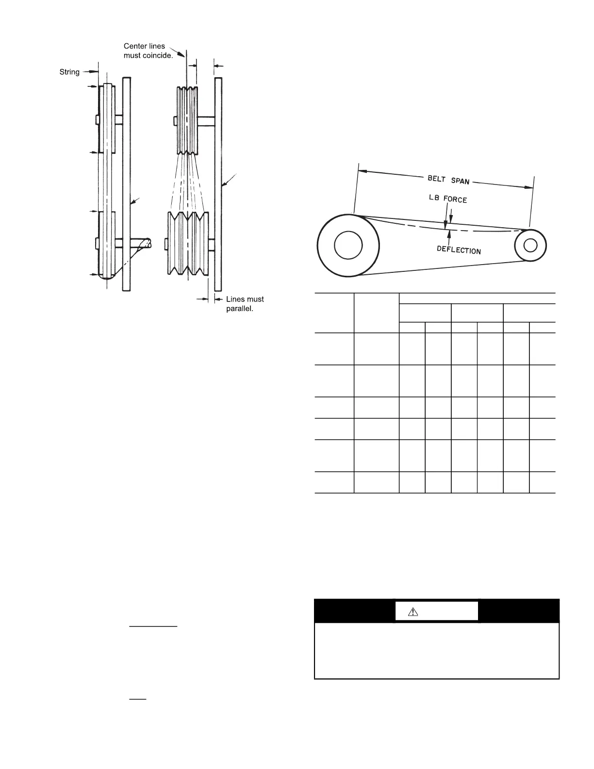
Fig. 48 — Sheave Alignment
Install V-Belts
When installing or replacing belts, always use a complete set of
new belts. Mixing old and new belts will result in the premature
wear or breakage of the newer belts.
1. Always adjust the motor position so that V-belts can be
installed without stretching over grooves. Forcing belts can
result in uneven stretching and a mismatched set of belts.
2. Do not allow belt to bottom out in sheave.
3. Tighten belts by turning motor-adjusting jackscrews. Turn
each jackscrew an equal number of turns.
4. Equalize belt slack so that it is on the same side of belt for all
belts. Failure to do so may result in uneven belt stretching.
5. Tension new drives at the maximum deflection force recom-
mended (Fig. 49).
6. To determine correct belt tension, use the deflection formula
given below and the tension data from Fig. 49 as follows:
EXAMPLE:
Given
Belt Span —16 in.
Belt Cross-Section A, Super Belt
Small Sheave Pitch Diameter — 5 in.
Solution
a. From Fig. 49 find that deflection force for type A, super
belt with 5 in. small sheave pitch diameter is 4 to 5-1/2lb.
b.
c. Increase or decrease belt tension until force required for
1/4 in. deflection is 5-1/2 lb.
d. Check belt tension at least twice during first operating
day. Readjust as required to maintain belt tension within
the recommended range.
With correct belt tension, belts may slip and squeal momentarily
on start up. This slippage is normal and disappears after unit
reaches operating speed. Excessive belt tension shortens belt life
and may cause bearing and shaft damage.
After run-in, set belt tension at lowest tension at which belts will
not slip during operation.
Fig. 49 — Fan Belt Tension Data
Water and Steam Coil Piping Recommendations
GENERAL
Use straps around the coil casing to lift and place the coil.
Piping practices are outlined in the Carrier System Design
Manual, Part 3, Piping Design.
Deflection =
(Belt Span)
64
Deflection =
16
64
Straight
Edge
Lines must be
parallel.
Bearing
Support
Channel
Fixed Sheave
Adjustable
Sheave
CAUTION
To prevent damage to the coil or coil headers: Do not use the
headers to lift the coil. Support the piping and coil connections
independently. Do not use the coil connections to support pip-
ing. When tightening coil connections, use a backup wrench
on the nozzles.
BELT
CROSS
SECTION
SMALL
SHEAVE
PD RANGE
(in.)
DEFLECTION FORCE — LB
Super Belts Notch Belts
Steel Cable
Belts
Min Max Min Max Min Max
A
3.0-3.6 3 4-1/4 3-7/8 5-1/2 3 4
3.8-4.8 3-1/2 5 4-1/2 6-1/4 3-3/4 4-3/4
5.0-7.0 4 5-1/2 5 6-7/8 41/4 51/4
B
3.4-4.2 4 5-1/2 5-3/4 8 4-1/2 5-1/2
4.4-5.6 5-1/8 7-1/8 6-1/2 9-1/8 5-3/4 7-1/4
5.8-8.6 6-3/8 8-3/4 7-3/8 10-1/8 7 8-3/4
C
7.0-9.4 11-1/4 14-3/8 13-3/4 17-7/8 11-1/4 14
9.6-16.0 14-1/8 18-1/2 15-1/4 20-1/4 14-1/4 17-3/4
3V
2.65-3.65 3-1/2 5 3-7/8 5-1/2 — —
4.12-6.90 4-3/4 6-7/8 5-1/4 7-7/8 — —
5V
4.40-6.70 — — 10 15 — —
7.1-10.9 10-1/2 15-3/4 12-7/8 18-3/4 — —
11.8-16.0 13 19-1/2 15 22 — —
8V
12.5-17.0 27 40-1/2 — — — —
18.0-22.4 30 45 — — — —
LEGEND
PD — Pitch Diameter (inches)
Bekijk gratis de handleiding van Carrier 39S, stel vragen en lees de antwoorden op veelvoorkomende problemen, of gebruik onze assistent om sneller informatie in de handleiding te vinden of uitleg te krijgen over specifieke functies.
Productinformatie
| Merk | Carrier |
| Model | 39S |
| Categorie | Niet gecategoriseerd |
| Taal | Nederlands |
| Grootte | 10967 MB |


