Carrier 39S handleiding
Handleiding
Je bekijkt pagina 38 van 64
38
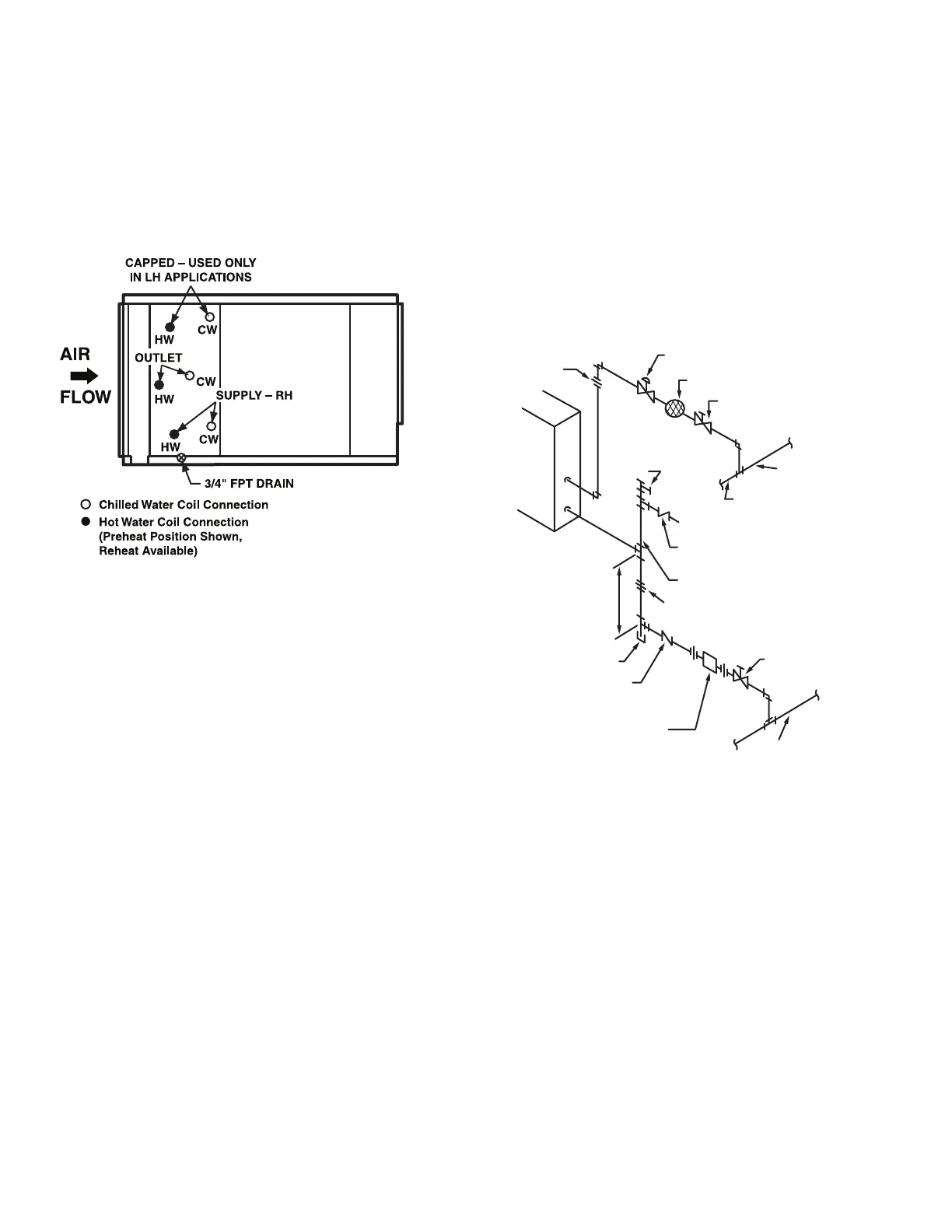
WATER COILS
Typically, coils are piped by connecting the supply at the bottom
and the return at the top. This is not always the case, especially if
the coil hand has been changed in the field. Coils must be piped
for counterflow; otherwise, a capacity reduction of 5% for each
coil row will result. To ensure counterflow, chilled water coils are
piped so that the coldest water meets the coldest air. Hot water
coils are piped so that the warmest water meets the warmest air.
Some 39S coils have 3 connections on either side of the coil (for a
total of 6 connections). In these cases, the middle connection is
used as the return connection. See Fig. 50.
.
Fig. 50 — Water Coil Connection
STEAM COILS
Position the steam supply connection at the top of the coil, and the
return (condensate) connection at the bottom.
Figure 51 illustrates the normal piping components and the sug-
gested locations for high, medium, or low-pressure steam coils.
The low-pressure application (zero to 15 psig) can dispense with
the 1/4 in. petcock for continuous venting located above the vacu-
um breaker (check valve).
NOTE: The horizontal location of the 15-degree check valve, and
the orientation of the gate/pivot. This valve is intended to relieve
any vacuum forming in the condensate outlet of a condensing
steam coil, and to seal this port when steam pressure is again sup-
plied to the coil. It must not be installed in any other position, and
should not be used in the supply line.
For coils used in tempering service, or to preheat outside air, in-
stall an immersion thermostat in the condensate line ahead of the
trap. This will shut down the supply fan and close the outdoor
damper whenever the condensate falls to a predetermined point,
perhaps 120°F.
NOTE: DO NOT use an immersion thermostat to override a duct
thermostat and open the steam supply valve.
For vacuum return systems, the vacuum breaking check valve
would be piped into the condensate line between the trap and the
gate valve instead of open to the atmosphere.
Figure 52 illustrates the typical piping at the end of every steam
supply main. Omitting this causes many field problems and failed
coils.
Figure 53 shows the typical field piping of multiple coils. Use this
only if the coils are the same size and have the same pressure drop.
If this is not the case, an individual trap must be provided for each
coil.
Figure 54 shows a multiple coil arrangement applied to a gravity
return, including the open air relief to the atmosphere, which
DOES NOT replace the vacuum breakers.
Figure 55 illustrates the basic condensate lift piping.
Fig. 51 — Low, Medium or High Pressure Coil Piping
LEGEND
CW — Chilled Water
HW — Hot Water
LH — Left Hand
RH — Right Hand
Note 1
Control Valve (Note 3)
Strainer
Gate Valve
Steam Supply
Main
*
15° Check Valve
For Breaking Vacuum
1/2 in. Line
Note 1
12 in.
Min.
Dirt Leg (6”)
15° Check Valve
Float Or
Bucket Trap
(Note 2)
Gate Valve
Condensate
Return Main
1/4 in. Pet Cock
For Continuous
Vent
Unit
*When end of supply main, see Fig. 52.
NOTES:
1. Flange or union is located to facilitate coil removal.
2. Flash trap may be used if pressure differential between steam
and condensate return exceeds 5 psi.
3. When a bypass with control is required.
4. Dirt leg may be replaced with a strainer. If so, tee on drop can
be replaced by a reducing ell.
5. The petcock is not necessary with a bucket trap or any trap
which has provision for passing air. The great majority of high
or medium pressure returns end in hot wells or de-aerators
which vent the air.
Bekijk gratis de handleiding van Carrier 39S, stel vragen en lees de antwoorden op veelvoorkomende problemen, of gebruik onze assistent om sneller informatie in de handleiding te vinden of uitleg te krijgen over specifieke functies.
Productinformatie
| Merk | Carrier |
| Model | 39S |
| Categorie | Niet gecategoriseerd |
| Taal | Nederlands |
| Grootte | 10967 MB |


