Carrier 39L handleiding
Handleiding
Je bekijkt pagina 27 van 76
27
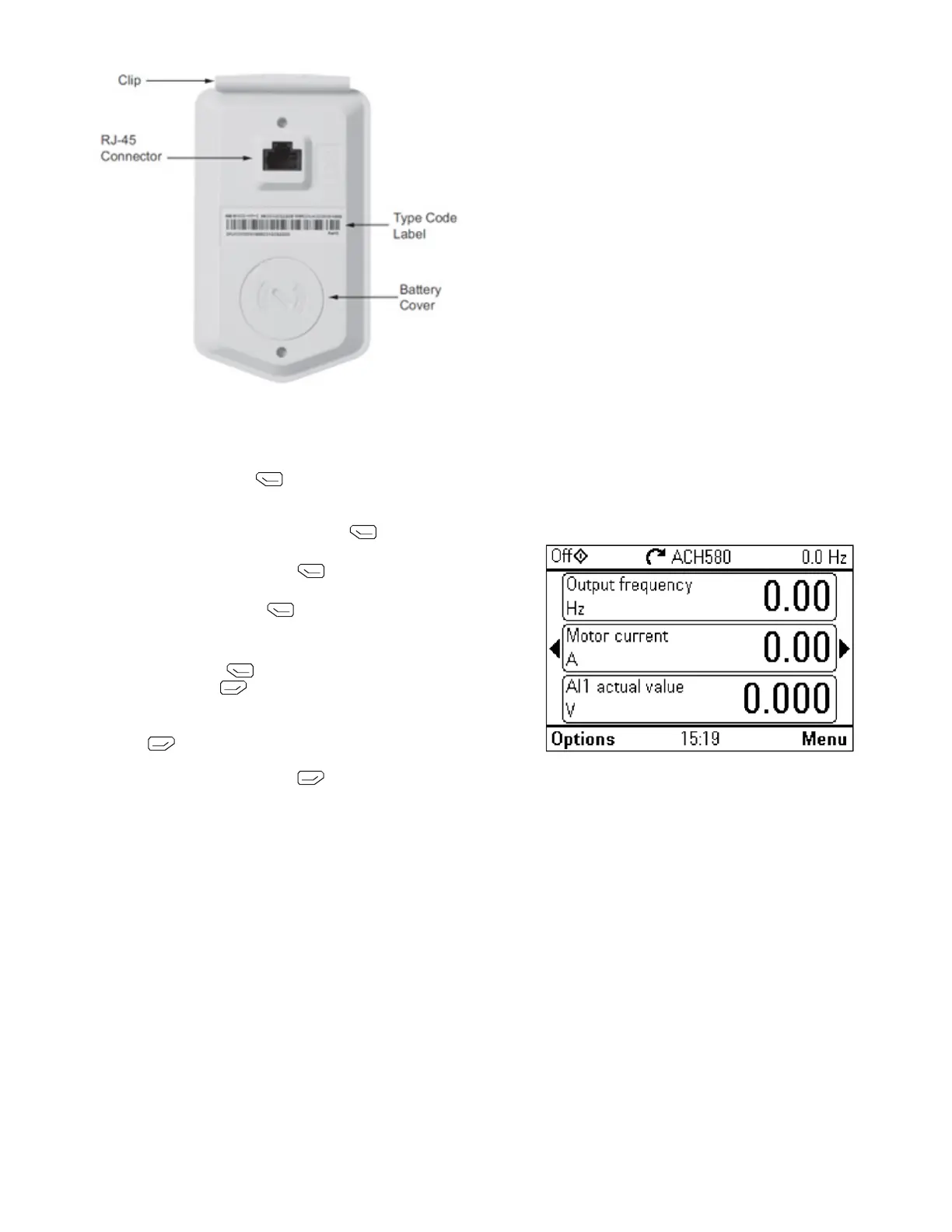
Fig. 25 — ACH580 VFD Keypad (Back)
START UP CHANGING PARAMETERS INDIVIDUALLY
Initial start-up is performed at the factory. To start up the VFD by
changing individual parameters, perform the following procedure:
1. Select MENU (Press ) The Main menu will be
displayed.
2. Use the UP or DOWN keys to highlight PARAMETERS on
the display screen and press SEL (Press
).
3. Use the UP or DOWN keys to highlight the desired parame-
ter group and press SEL (Press ).
4. Use the UP or DOWN keys to highlight the desired parame-
ter and press EDIT (Press ).
5. Use the UP or DOWN keys to change the value of the
parameter.
6. Press SAVE (Press ) to store the modified value. Press
CANCEL (Press ) to keep the previous value. Any
modifications that are not saved will not be changed.
7. Choose another parameter or press EXIT/BACK
(Press
) to return to the listing of parameter groups.
Continue until all the parameters have been configured and
then press EXIT/BACK (Press
) to return to the main
menu.
NOTE: The current parameter value appears above the highlight
parameter. To view the default parameter value, press the UP and
DOWN keys simultaneously.
VFD MODES
The VFD has several different modes for configuring, operating,
and diagnosing the VFD.
The modes are:
• Standard Display mode - shows drive status information
and operates the drive
• Parameters mode - edits parameter values individually
• Start-up Assistant mode - guides start-up and configuration
• Changed Parameters mode - shows all changed parameters
• Drive Parameter Backup mode - stores or uploads the
parameters
• Clock Set mode - sets the time and date for the drive
• I/O Settings mode - checks and edits the I/O settings
ACH580 STANDARD DISPLAY MODE
Use the standard display mode to read information on the drive
status and operate the drive. To reach the standard display mode,
press BACK until the LCD display shows status information as
described below. (See Fig.
26.)
The top line of the LCD display shows the basic status informa-
tion of the drive. The HAND icon indicates that the drive control
is local from the control panel. The AUTO icon indicates that the
drive is in remote control mode, such as the basic I/O or field bus.
The arrow icon indicates the drive and motor rotation status. A ro-
tating arrow (clockwise or counterclockwise) indicates that the
drive is running and at set point and the shaft direction is forward
or reverse. A rotating blinking arrow indicates that the drive is
running but not at set point. A stationary arrow indicates that the
drive is stopped. For the units covered in this manual, the correct
display rotation is clockwise.
The upper right corner shows the frequency set point that the drive
will maintain. From Home view press Options then Edit Home
View to change the Home layout, the middle of the LCD display
can be configured to display 3 parameter values, Graphs or digital
indicators. The default display shows (OUTPUT FREQ) in per
-
cent speed, (CURRENT) in amperes, and (Al1) in voltage DC.
The bottom corners of the LCD display show the functions cur-
rently assigned to the two soft keys. The lower middle displays the
current time (if configured to show the time).
The first time the drive is powered up, it is in the OFF mode. To
switch to local hand-held control and control the drive using the
control panel, press and hold the HAND button. Pressing the
HAND button switches the drive to hand control while keeping
the drive running. Press the AUTO button to switch to remote
input control. To start the drive press the HAND or AUTO but
-
tons, to stop the drive press the OFF button.
Fig. 26 — Standard Display Example
The top line of the LCD display shows the basic status informa-
tion of the drive. The HAND icon indicates that the drive control
is local from the control panel. The AUTO icon indicates that the
drive is in remote control mode, such as the basic I/O or field bus.
The arrow icon indicates the drive and motor rotation status. A ro-
tating arrow (clockwise or counterclockwise) indicates that the
drive is running and at set point and the shaft direction is forward
or reverse. A rotating blinking arrow indicates that the drive is
running but not at set point. A stationary arrow indicates that the
drive is stopped. For the units covered in this manual, the correct
display rotation is clockwise.
The upper right corner shows the frequency set point that the drive
will maintain.
From Home view press Options then Edit Home View to change
the home layout, the middle of the LCD display can be configured
to display 3 parameter values, Graphs or digital indicators. The de
-
fault display shows (OUTPUT FREQ) in percent speed, (CUR-
RENT) in amperes, and (Al1) in voltage DC.
The bottom corners of the LCD display show the functions cur-
rently assigned to the two soft keys. The lower middle displays the
current time (if configured to show the time).
The first time the drive is powered up, it is in the OFF mode. To
switch to local hand-held control and control the drive using the
Bekijk gratis de handleiding van Carrier 39L, stel vragen en lees de antwoorden op veelvoorkomende problemen, of gebruik onze assistent om sneller informatie in de handleiding te vinden of uitleg te krijgen over specifieke functies.
Productinformatie
| Merk | Carrier |
| Model | 39L |
| Categorie | Niet gecategoriseerd |
| Taal | Nederlands |
| Grootte | 14640 MB |


