Carrier WeatherMaker 50FE handleiding
Handleiding
Je bekijkt pagina 32 van 72
32
24-v source (no “C” connection required), use a thermostat cable
or equivalent with minimum of six leads. Check the thermostat in-
stallation instructions for additional features which might require
additional conductors in the cable.
For wire runs up to 50 ft (15 m), use no. 18 AWG (American Wire
Gage) insulated wire (35°C minimum). For 50 to 75 ft (15 to
23 m), use no. 16 AWG insulated wire (35°C minimum). For over
75 ft (23 m), use no. 14 AWG insulated wire (35°C minimum). All
wire sizes larger than no. 18 AWG cannot be directly connected to
the thermostat and will require a junction box and splice at the
thermostat.
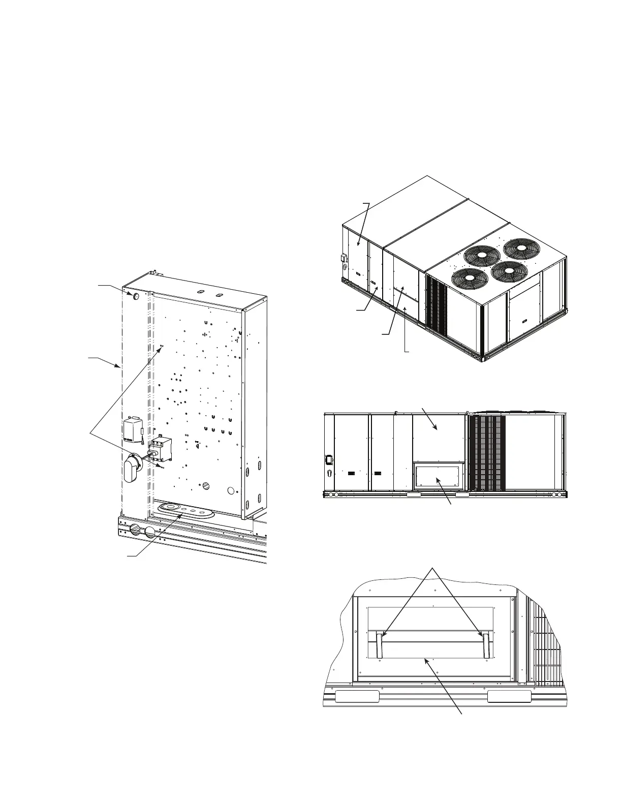
Unit Without Thru-Base Connection Kit
Correctly rated low voltage wire can be routed through the rubber
grommet located on the corner post adjacent to the control box ac-
cess panel. Route wire through the grommet and then route the
wire behind the corner post utilizing the factory provided wire ties
secured to the control box. This will ensure separation of the field
low voltage wire and the high voltage circuit. Route the low volt-
age wire to the central terminal board. See Fig. 48.
NOTE: If utilizing the through the base connections, route the low
voltage wire through the wire ties to the central terminal board.
Fig. 48 — Field Control Wiring Raceway
Configure for Electric Heat
To configure the factory-approved thermostat, open the Advanced
Setup menu, scroll down to ELECTRIC HEAT and change
RANGE value from OFF to ON. Consult the thermostat installa-
tion instructions for full details.
Heat Anticipator Settings
Set heat anticipator settings at 0.14 amp for the first stage and
0.14 amp for second-stage heating.
Transformer Connection for 208-v Power Supply
All units except 208/230-v units are factory wired for the voltage
shown on the nameplate. If the 208/230-v unit is to be connected
to a 208-v power supply, the control transformer must be rewired
by moving the black wire with the 1/4 in. female spade connector
from the 230-v connection and moving it to the 208-v 1/4 in. male
terminal on the primary side of the transformer. Refer to unit label
diagram for additional information.
ELECTRIC HEATERS
The 50FE units may be equipped with field-installed accessory
electric heaters. The heaters are modular in design.
Heater modules are installed in the compartment below the indoor
blower access panel. Access is through the electric heat access
panel. Heater modules slide into the compartment on tracks along
the bottom of the heater opening. See Fig. 49-51. Refer to the
Electric Heater Kit Installation Instructions for complete details.
Not all available heater modules may be used in every unit. Use
only those heater modules that are approved for use in a specific
size unit. Refer to the label on the unit cabinet for the list of ap-
proved heaters.
Fig. 49 — Typical Access Panel Locations
Fig. 50 — Electric Heater Compartment
with Cover Plate
Fig. 51 — Electric Heater Compartment
(Cover Plate Removed)
Rubber
Grommet
Corner
Post
Wire
Ties
Thru-the-Base
Connection
Control Box
Access
Panel
Filter and
Indoor Coil
Access
Panel
Indoor Blower
Access Panel
Electric Heat
Access Panel
Indoor Blower
Access Panel
Electric Heater
Cover Plate
Electric Heater Tracks
Electric Heater
Opening
Bekijk gratis de handleiding van Carrier WeatherMaker 50FE, stel vragen en lees de antwoorden op veelvoorkomende problemen, of gebruik onze assistent om sneller informatie in de handleiding te vinden of uitleg te krijgen over specifieke functies.
Productinformatie
| Merk | Carrier |
| Model | WeatherMaker 50FE |
| Categorie | Niet gecategoriseerd |
| Taal | Nederlands |
| Grootte | 9321 MB |


