Carrier WeatherMaker 50FE handleiding
Handleiding
Je bekijkt pagina 30 van 72
30
Determine maximum deviation from average voltage.
(AB) 227-224 = 3-v
(BC) 231-227 = 4-v
(AC) 227-226 = 1-v
Maximum deviation is 4-v.
Determine percent of voltage imbalance.
This amount of phase imbalance is satisfactory as it is below the maximum
allowable 2%.
CONVENIENCE OUTLETS
Two types of convenience outlets are offered on 50FE models:
non-unit powered and unit-powered. Both types provide a 125-v
GFCI (ground-fault circuit-interrupter) duplex receptacle rated at
15-A behind a hinged access cover, located on the corner panel of
the unit. See Fig. 43.
Fig. 43 — Convenience Outlet Location
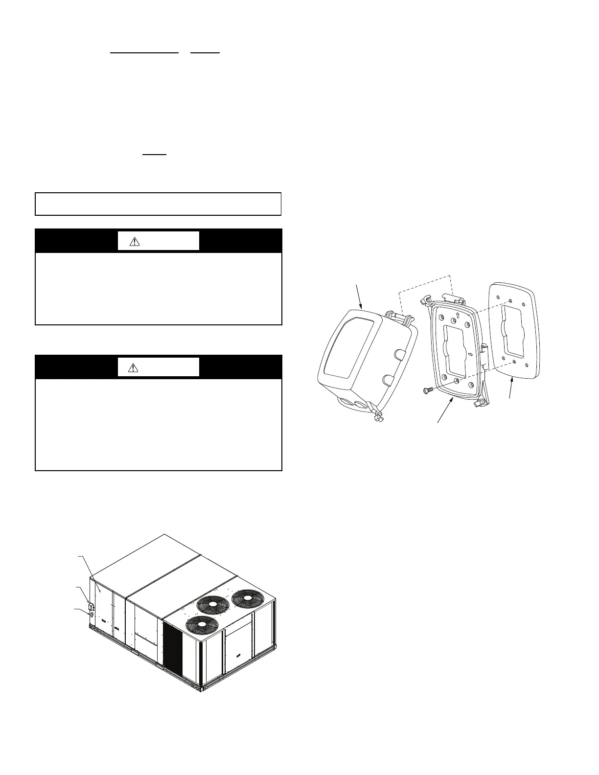
Installing Weatherproof Cover
A weatherproof while-in-use cover for the factory-installed conve-
nience outlets is now required by UL standards. This cover cannot
be factory-mounted due to its depth; it must be installed at unit in-
stallation. For shipment, the convenience outlet is covered with a
blank cover plate.
The weatherproof cover kit is shipped in the unit’s control box.
The kit includes the hinged cover, a backing plate and gasket.
Disconnect all power to unit and convenience outlet. Lock-out and
tag-out all power.
Remove the blank cover plate at the convenience outlet; discard
the blank cover.
Loosen the two screws at the GFCI duplex outlet, until approxi-
mately 1/2 in. (13 mm) under screw heads are exposed. Press the
gasket over the screw heads. Slip the backing plate over the screw
heads at the keyhole slots and align with the gasket; tighten the
two screws until snug (do not over-tighten).
Mount the weatherproof cover to the backing plate as shown in
Fig. 44. Remove two slot fillers in the bottom of the cover to per-
mit service tool cords to exit the cover. Check for full closing and
latching.
Fig. 44 — Weatherproof Cover Installation
Non unit-powered type
Requires the field installation of a general-purpose 125-v 15-A
circuit powered from a source elsewhere in the building. Observe
national and local codes when selecting wire size, fuse or breaker
requirements and disconnect switch size and location. Route
125-v power supply conductors into the bottom of the utility box
containing the duplex receptacle.
Unit-powered type
A unit-mounted transformer which is factory-installed to step-
down the main power supply voltage to the unit to 115-v at the du-
plex receptacle. This option also includes a manual switch with
fuse, located in a utility box and mounted on a bracket behind the
convenience outlet; access is through the unit’s control box access
panel. See Fig. 45.
The primary leads to the convenience outlet transformer are not
factory-connected. If local codes permit, the transformer primary
leads can be connected at the line-side terminals on the unit-
mounted non-fused disconnect switch; this will provide service
power to the unit when the unit disconnect switch is open. See
Fig. 45. See Fig. 46 for convenience outlet utilization precautions.
Test the GFCI receptacle by pressing the TEST button on the face
of the receptacle to trip and open the receptacle. Check for proper
grounding wires and power line phasing if the GFCI receptacle
does not trip as required. Press the RESET button to clear the
tripped condition.
Average Voltage =
(224 + 231 + 226)
=
681
= 227
33
% Voltage Imbalance = 100x
4
= 1.76%
227
IMPORTANT: If the supply voltage phase imbalance is more than 2%, contact
your local electric utility company immediately.
CAUTION
UNIT DAMAGE HAZARD
Failure to follow this caution may result in equipment damage.
Operation on improper line voltage or excessive phase
imbalance constitutes abuse and may cause damage to
electrical components. Such operation would invalidate any
applicable Carrier warranty.
WARNING
ELECTRICAL OPERATION HAZARD
Failure to follow this warning could result in personal injury or
death.
Units with convenience outlet circuits may use multiple
disconnects. Check convenience outlet for power status before
opening unit for service. Locate its disconnect switch, if
appropriate, and open it. Lock-out and tag-out this switch, if
necessary.
Convenience
Outlet
Electric
Disconnect
Switch
Control Box
Access
Panel
Cover — While-In-Use
Weatherproof
Baseplate For
GFCI Receptacle
Gasket
GFCI Receptacle
Not Included
T
O
P
TO
P
TOP
W
E
T
LOC
A
TI
O
N
S
W
E
T
L
O
C
A
TI
O
N
S
Bekijk gratis de handleiding van Carrier WeatherMaker 50FE, stel vragen en lees de antwoorden op veelvoorkomende problemen, of gebruik onze assistent om sneller informatie in de handleiding te vinden of uitleg te krijgen over specifieke functies.
Productinformatie
| Merk | Carrier |
| Model | WeatherMaker 50FE |
| Categorie | Niet gecategoriseerd |
| Taal | Nederlands |
| Grootte | 9321 MB |


