Carrier WeatherMaker 50FC handleiding
Handleiding
Je bekijkt pagina 46 van 68
46
Cooling Delay via Increasing Fan Speed
If there is cooling demand while outside air is suitable for
economizing, then the economizer controller tries to increase
fan speed to maximize the use of outside air first. If the cooling
demand is not reached within a set time, then mechanical cool-
ing will be enabled.
Typical field application:
1. Prerequisites:
a. Outside air is suitable for economizing and free cool-
ing is ON.
b. Fan connected to the controller supports multiple
speeds. Cooling delay function does not work if only
a one-speed fan is connected to the controller.
2. If it is a 2-speed fan and there are 2 cooling demand
inputs/outputs, when Y1-Input is called, the controller sets
fan speed to Speed Low. Damper is fully open (100%).
If Y2-Input is also called, then the controller increases fan
speed to Speed High and starts fan delay (2FAN DLY)
time. After the delay time runs out, the controller starts
Y1-Output.
Demand Controlled Ventilation (DCV)
If a field-installed CO
2
sensor is connected to the
EconomizerONE controller, then a demand-controlled ventilation
strategy will operate automatically. As the CO
2
level in the space
increases above the set point (on the EconomizerONE controller),
the minimum position of the dampers will be increased propor-
tionally until the Maximum Ventilation setting is reached. As the
space CO
2
level decreases because of the increase in fresh air, the
outdoor damper will follow the higher demand condition from the
DCV mode or from the free cooling mode.
The controller modulates the outside air damper based on the CO
2
level through the ppm value selected between the range of 500 and
2000 ppm. The measured CO
2
concentration value is compared
with the set DCV set point. If the measured CO
2
concentration
value is below the DCV set point, keep the damper to the
minimum position. Otherwise, enable DCV. Once DCV is en-
abled, the DCV PID starts to run to control the indoor CO
2
concentration value towards the DCV set point. The damper opens
to the maximum position.
NOTE: DCV is disabled if the controller receives no occupancy
signal.
DCV operation is available in Occupied and Unoccupied peri-
ods with EconomizerONE system. However, a control modifi-
cation will be required on the unit system to implement the Un-
occupied period function. Refer to controller accessory instal-
lation instruction manual for further controls and command
operation information.
High Humidity Limitation
The economizer controller applies high limit of humidity to
enthalpy-based economizing. When the OA dew point is below
the dew point set point, enthalpy-based economizing is avail-
able. Otherwise, enthalpy-based economizing is unavailable.
Anti-Freeze Protection
The economizer controller initiates the anti-freeze protection if
MAT or OAT temperature falls below the anti-freeze set point.
MAT-Based Anti-Freeze Protection
1. If MAT temperature falls below the anti-freeze set point
(3FRZ PROT) and:
• If unit type is conventional unit and cooling/heating con-
ventional operation mode is enabled, then the controller
closes both damper and compressor.
• If unit type is heat pump and heat pump operation mode is
enabled, then the controller closes the damper.
2. If the MAT sensor fails, MAT is substituted by OAT to con-
tinue the anti-freeze assessment. If OAT sensor also fails,
then the controller closes the damper immediately.
OAT-Based Anti-Freeze Protection
If OAT temperature falls below the OAT lockout set point
(3OAT
LOCK) and:
1. If unit type is conventional unit and cooling/heating con-
ventional operation mode is enabled, then the controller
stops the compressor from running.
2. If unit type is heat pump and heat pump operation mode is
enabled, then the controller compressor is bypassed.
Exhaust Fan Operation
Up to 2 exhaust fans can be connected to the economizer
controller.
• If Exhaust Fan 1 is connected and configured, then
Exhaust Fan 1 parameter group (L, M, and H) is available,
depending on fan configuration.
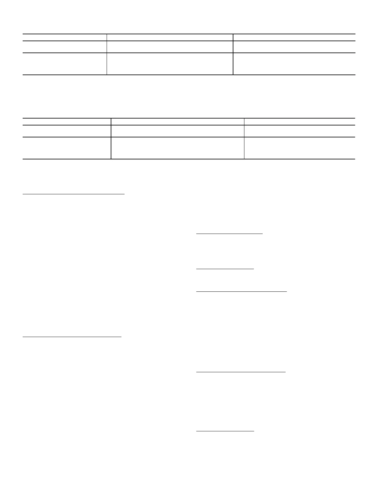
Table 11 — Different Damper Position Setting with Different Configured Outputs (DCV is Enabled)
FAN TYPE 1-STAGE COOLING
a
NOTE(S):
a. Configured by Y1O or Y2O.
2-STAGE COOLING
a
1-SPEED FAN
b
b. Configured by 6FAN.
• 2VENTMIN H to 2VENTMAX H (regardless of
cooling demand, OCC=Yes)
• 2VENTMIN H to 2VENTMAX H (regardless of
cooling demand, OCC=Yes)
2-SPEED FAN
b
• 2VENTMIN H to 2VENTMAX H (regardless of
cooling demand, OCC=Yes)
• 2VENTMIN L to 2VENTMAXL
(0 or 1 cooling demand)
• 2VENTMIN H to 2VENTMAX H
(2 cooling demands)
Table 12 — Different Damper Position Setting with Different Configured Outputs
(DCV is Disabled, CO
2
sensor is connected)
FAN TYPE 1-STAGE COOLING
a
NOTE(S):
a. Configured by Y1O or Y2O.
2-STAGE COOLING
a
1-SPEED FAN
b
b. Configured by 6FAN.
• 2VENTMIN H (regardless of cooling demand,
OCC=Yes)
• 2VENTMIN H (regardless of cooling demand,
OCC=Yes)
2-SPEED FAN
b
• 2VENTMIN H (regardless of cooling demand,
OCC=Yes)
•2VENTMIN L
(0 or 1 cooling demand)
• 2VENTMIN H
(2 cooling demands)
Bekijk gratis de handleiding van Carrier WeatherMaker 50FC, stel vragen en lees de antwoorden op veelvoorkomende problemen, of gebruik onze assistent om sneller informatie in de handleiding te vinden of uitleg te krijgen over specifieke functies.
Productinformatie
| Merk | Carrier |
| Model | WeatherMaker 50FC |
| Categorie | Niet gecategoriseerd |
| Taal | Nederlands |
| Grootte | 8511 MB |


