Carrier WeatherMaker 48FE handleiding
Handleiding
Je bekijkt pagina 36 van 80
36
Humidi-MiZer
®
System Control Connections
HUMIDI-MIZER — SPACE RH CONTROLLER
NOTE: The Humidi-MiZer
®
system is a factory-installed option.
The Humidi-MiZer dehumidification system requires a field-
supplied and installed space relative humidity control device. This
device may be a separate humidistat control (contact closes on rise
in space RH above control setpoint, see Fig. 54) or a combination
thermostat-humidistat control device such as Carrier’s Edge
®
Pro
Thermidistat™ device with isolated contact set for dehumidifica-
tion control (see Fig. 55). The humidistat is normally used in ap-
plications where a temperature control is already provided (units
with SystemVu™ control).
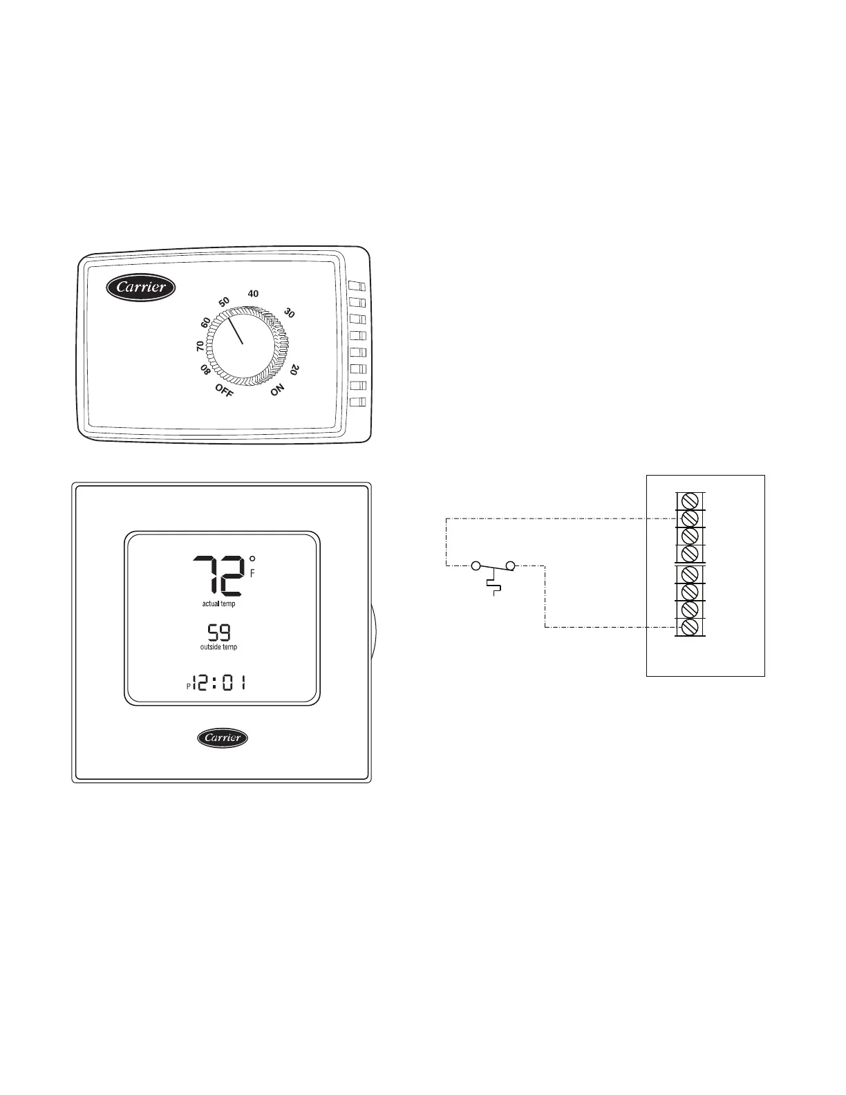
Fig. 54 — Accessory Field-Installed Humidistat
Fig. 55 — Edge
®
Pro Thermidistat
To connect the Carrier humidistat (HL38MG029):
1. Route the humidistat 2-conductor cable (field-supplied)
through hole provided in the unit corner post.
2. Feed wires through the raceway built into the corner post (see
Fig. 53) to the 24 v barrier located on the left side of the con-
trol box. The raceway provides the UL-required clearance
between high-voltage and low-voltage wiring.
3. Connect one of the leads from the 2-conductor cable to the
HUM terminal on the UCB (Unit Control Board). Connect
the other lead to the R terminal on the UCB. See Fig. 56.
To connect the Thermidistat device (33CS2PPRH-01):
1. Route the Thermidistat multi-conductor thermostat cable
(field-supplied) through hole provided in the unit corner post.
2. Feed wires through the raceway built into the corner post (see
Fig. 53) to the 24 v barrier located on the left side of the con-
trol box. The raceway provides the UL-required clearance
between high-voltage and low-voltage wiring.
3. The Thermidistat has dry contacts at terminals D1 and D2
for dehumidification operation (see Fig. 57). Connect D1 to
the R terminal on the UCB. Connect D2 to the HUM termi-
nal on the UCB. Refer to the installation instructions
included with the Carrier Edge
®
Pro Thermidistat device for
more information.
Fig. 56 — Humidistat Connections to UCB
Typical Unit Wiring Diagrams
See Fig. 58-63 for examples of typical unit control and power wir-
ing diagrams. These wiring diagrams are mounted on the inside of
the unit control box. Refer to the wiring diagrams in the unit con-
trol box when making field power wiring connections.
% RELATIVE HUMIDITY
®
Humidistat
Unit Control
Board
Thermostat
C
HUM
G
W2
W1
Y2
Y1
R
Bekijk gratis de handleiding van Carrier WeatherMaker 48FE, stel vragen en lees de antwoorden op veelvoorkomende problemen, of gebruik onze assistent om sneller informatie in de handleiding te vinden of uitleg te krijgen over specifieke functies.
Productinformatie
| Merk | Carrier |
| Model | WeatherMaker 48FE |
| Categorie | Niet gecategoriseerd |
| Taal | Nederlands |
| Grootte | 10304 MB |


