Carrier WeatherMaker 48FE handleiding
Handleiding
Je bekijkt pagina 30 van 80
30
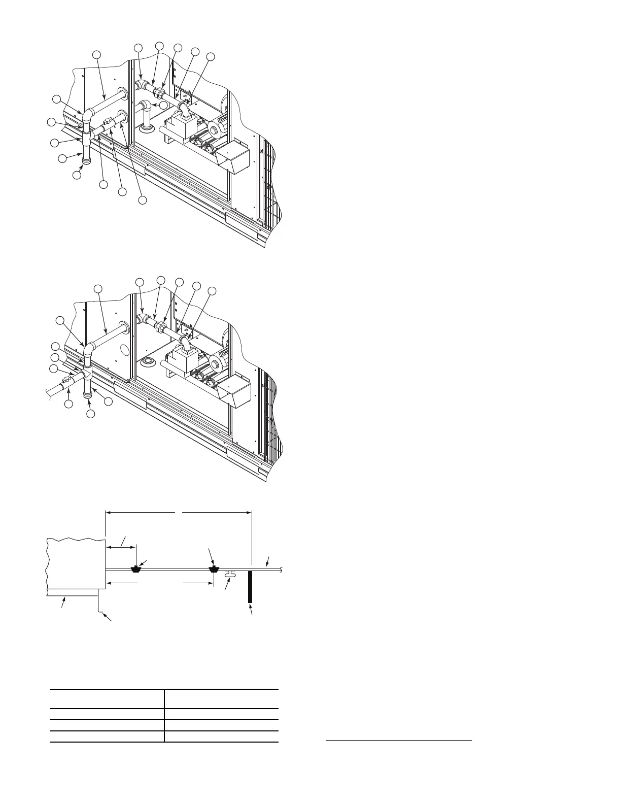
Fig. 38 — Gas Supply Line Piping with Thru-Base
Fig. 39 — Gas Supply Line Piping
Fig. 40 — Gas Piping Guide
FACTORY OPTION THRU-BASE CONNECTIONS
Electrical Connections
Knockouts are located in the control box area. Remove the appro-
priate size knockout for high voltage connection. Use the field
supplied connector depending on wiring or conduit being utilized.
Remove the 7/8 in. (22 mm) knockout and appropriate connector
for low voltage wiring. If non-unit powered convenience outlet is
being utilized, remove the 7/8 in. (22 mm) knockout and utilize
appropriate connector for 115 volt line. See “Install External Con-
densate Trap and Line” on page 31 for details.
Gas Connections
Remove the knockout in the base pan and route 3/4 in. gas line up
through the opening. Install an elbow and route gas line through
opening in panel after first removing plastic bushing. Install a gas
shut off followed by a drip leg and ground-joint union. Route gas
line into gas section through the grommet (Part #: KA56SL112) at
the gas inlet and into the gas valve. See Fig. 38 and Table 7. If a
regulator is installed, it must be located 4 ft (1.22 meters) from the
flue outlet.
Some municipal codes require that the manual shutoff valve be lo-
cated upstream of the sediment trap. See Fig. 39 for typical piping
arrangements for gas piping that has been routed through the side-
wall of the base pan.
When installing the gas supply line, observe local codes pertaining
to gas pipe installations. Refer to the NFPA 54/ANSI Z223.1
NFGC latest edition (in Canada, CAN/CSA B149.1). In the ab-
sence of local building codes, adhere to the following pertinent
recommendations:
1. Avoid low spots in long runs of pipe. Grade all pipe 1/4 in.
every 15 ft (7 mm in every 5 m) to prevent traps. Grade all
horizontal runs downward to risers. Use risers to connect to
heating section and to meter.
2. Protect all segments of piping system against physical and
thermal damage. Support all piping with appropriate straps,
hangers, etc. Use a minimum of one hanger every 6 ft
(1.8 m). For pipe sizes larger than 1/2 in., follow recommen-
dations of national codes.
3. Apply joint compound (pipe dope) sparingly and only to
male threads of joint when making pipe connections. Use
only pipe dope that is resistant to action of liquefied petro-
leum gases as specified by local and/or national codes. If
using PTFE (Teflon
®1
) tape, ensure the material is Double
Density type and is labeled for use on gas lines. Apply tape
per manufacturer’s instructions.
4. Pressure-test all gas piping in accordance with local and
national plumbing and gas codes before connecting piping to
unit.
NOTE: Pressure test the gas supply system after the gas supply
piping is connected to the gas valve. The supply piping must be
disconnected from the gas valve during the testing of the piping
systems when test pressure is in excess of 0.5 psig (3450 Pa). Pres-
sure test the gas supply piping system at pressures equal to or less
than 0.5 psig (3450 Pa). The unit heating section must be isolated
from the gas piping system by closing the external main manual
shutoff valve and slightly opening the ground-joint union.
Check for gas leaks at the field-installed and factory-installed gas
lines after all piping connections have been completed. Use soap-
and-water solution (or method specified by local codes and/or
regulations).
15
14
13
12
11
10
9
8
7
6
5
4
3
2
1
13
12
11
10
9
8
7
6
5
4
3
2
1
STEEL PIPE NOMINAL
DIAMETER (in.)
SPACING OF SUPPORTS X
DIMENSION (ft)
1/2 6
3/4 or 1 8
1 1/4 or larger 10
LEGEND
NFGC — National Fuel Gas Code
* Field supplied.
NOTE: Follow all local codes.
X
Base Unit
Base Rail
Roof
Curb
9” Minimum Clearance
For Panel Removal
Manual Gas
Shutoff Valve
*
Gas
Regulator
*
48” Minimum
Drip Leg
Per NFGC
*
Field-
Fabricated
Support
*
From
Gas
Meter
1. Third-party trademarks and logos are the property of their respective
owners.
Bekijk gratis de handleiding van Carrier WeatherMaker 48FE, stel vragen en lees de antwoorden op veelvoorkomende problemen, of gebruik onze assistent om sneller informatie in de handleiding te vinden of uitleg te krijgen over specifieke functies.
Productinformatie
| Merk | Carrier |
| Model | WeatherMaker 48FE |
| Categorie | Niet gecategoriseerd |
| Taal | Nederlands |
| Grootte | 10304 MB |


