Carrier NSA-DIFFER-LO handleiding
Handleiding
Je bekijkt pagina 6 van 9
Differential Low Pressure
Installation and Operation
#NSA-HH/DLP-001-W-U-D-A-3-C, NSA-HH/DLP-001-W-U-N-A-0-C, NSA-HH/DLP-010-W-U-D-A-3-C
NSA-HH/DLP-010-W-U-N-A-0-C, NSA-HH/DLP-040-W-U-D-A-3-C, NSA-HH/DLP-040-W-U-N-A-0-C – 11/14/2019
Specifications subject to change without notice.
Catalog No. 11-808-753-01 Page 6 of 9
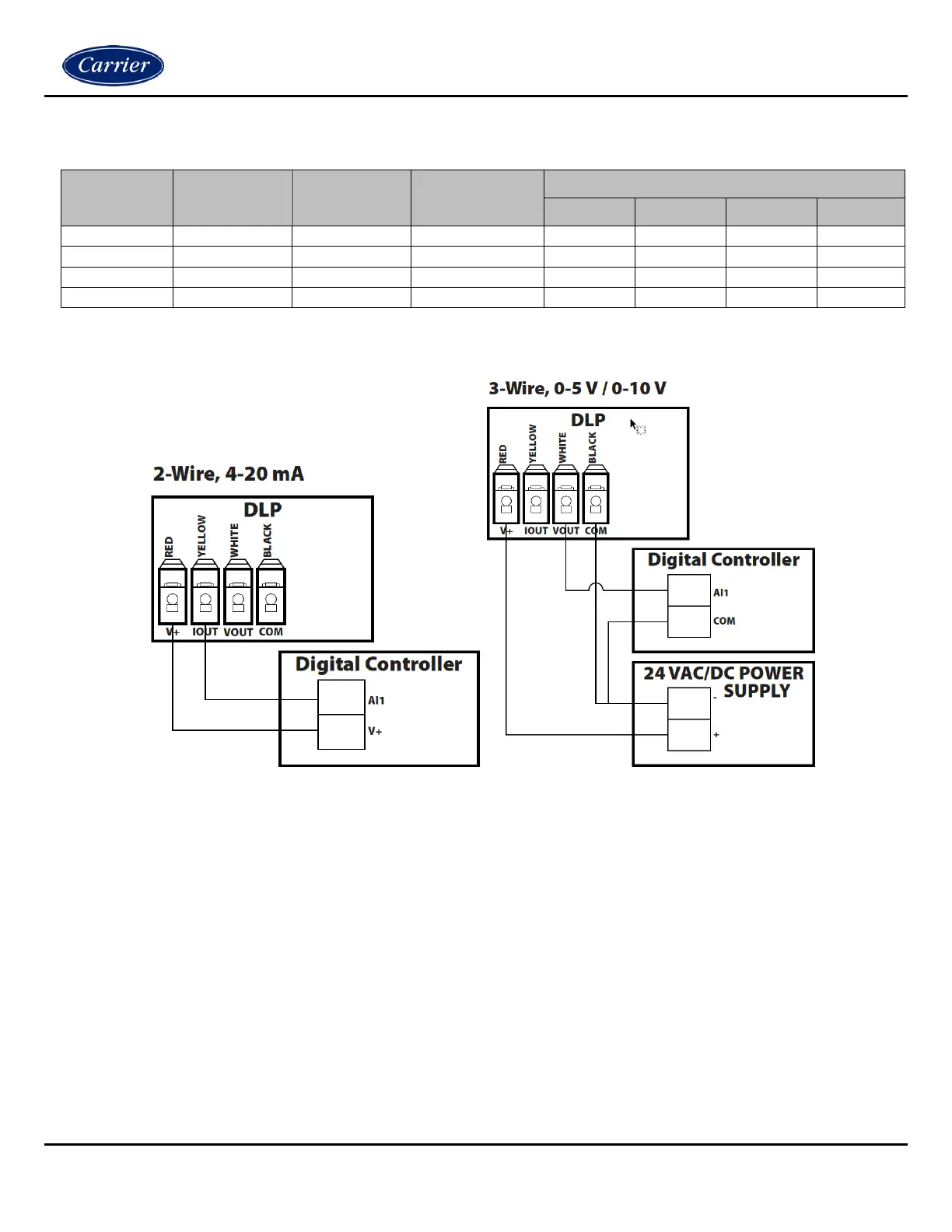
Wiring Connections
Output
Signal
Output Mode
(SW1)
Output Signal
(SW Pos 4)
Supply Voltage
Wire Connections
Red
Black
White
Yellow
0-5 VDC
Vout
5 V
VAC/VDC
V+
COM
VOUT
N/C
0-10 VDC
Vout
10 V
VAC/VDC
V+
COM
VOUT
N/C
4-20 mA
mA
N/A
VDC
V+
N/C
N/C
IOUT
4-20 mA
mA
N/A
VAC
V+
COM
N/C
IOUT
N/A = Not Applicable
N/C = No Connection
Figure 7
Open the cover of the enclosure. Carrier recommends 16 to 26 AWG twisted pair wires or shielded cable for all
transmitters. Twisted pair may be used for 2-wire current output transmitters or 3-wire for voltage output. Connect the wires
to the unit’s finger push-button terminal blocks. Each DLP unit can be configured to three output signals: 4-20 mA, 0-5 V or
0-10 V. Use the Wiring Connections and diagrams to determine the proper wiring for your application. See the Wiring
Connections table above for Output Mode and Output Signal switch positions.
NOTES
When using 1/2” conduit, the strain relief fitting must be removed from the enclosure.
Make sure that any conduit or metal fittings do not come in contact with the circuit board.
Bekijk gratis de handleiding van Carrier NSA-DIFFER-LO, stel vragen en lees de antwoorden op veelvoorkomende problemen, of gebruik onze assistent om sneller informatie in de handleiding te vinden of uitleg te krijgen over specifieke functies.
Productinformatie
| Merk | Carrier |
| Model | NSA-DIFFER-LO |
| Categorie | Niet gecategoriseerd |
| Taal | Nederlands |
| Grootte | 1501 MB |


