Carrier Aquazone 50WD handleiding
Handleiding
Je bekijkt pagina 51 van 84
51
ANTIFREEZE
In areas where leaving water temperatures drop below 40°F or
where piping will be routed through areas subject to freezing, anti-
freeze is needed.
Alcohols and glycols are commonly used as antifreeze agents.
Freeze protection should be maintained to 15°F below the lowest
expected entering loop temperature. For example, if the lowest
expected entering loop temperature is 30°F, the leaving loop
temperature would be 22 to 25°F. Therefore, the freeze protection
should be at 15°F (30°F – 15°F = 15°F).
NOTE: All alcohols should be pre-mixed and pumped from a
reservoir outside of the building or introduced under water level to
prevent fuming.
Calculate the total volume of fluid in the piping system
(see Table 19). Use the percentage by volume in Table 20 to
determine the amount of antifreeze to use. Antifreeze concentra-
tion should be checked from a well-mixed sample using a
hydrometer to measure specific gravity.
FREEZE PROTECTION SELECTION
The 25°F FP1 factory setting (water) should be used to avoid
freeze damage to the unit.
Once antifreeze is selected, refer to the Step 9 — “Configure Unit
Control Components” on page 24 of this manual for FREEZE
Protection settings on the UPM board.
START-UP
Use the procedure outlined below to initiate proper unit start-up.
Operating Limits
ENVIRONMENT
This equipment is designed for indoor installation only. Extreme
variations in temperature, humidity and corrosive water or air will
adversely affect the unit performance, reliability and service life.
NOTE: These operating limits are not normal or continuous
operating conditions. Assume that such a start-up is for the
purpose of bringing the building space up to occupancy
temperature. See Table 21 for operating limits.
POWER SUPPLY
A voltage variation of ± 10% of nameplate utilization voltage is
acceptable.
UNIT STARTING CONDITIONS
Depending on the model, units should start and operate with
entering water temperature temperatures between 20 and 110°F
and entering air temperatures between 45 and 95°F. Water flow
rates should be between 1.5 and 3.0 GPM/nominal cooling ton.
NOTE: Two factors determine the operating limits of a unit:
entering-air temperature and water temperature. Whenever any of
these factors are at a minimum or maximum level, the other fac-
tor must be at a normal level to ensure proper unit operation.
See Tables 22-33.
Start-Up Procedure
1. Restore power to system.
2. Turn thermostat blower position to ON or use the DDC
interface to enable the unit blower. The blower should start.
3. Balance airflow at diffusers/dampers.
4. Adjust all water valves to the full open position.
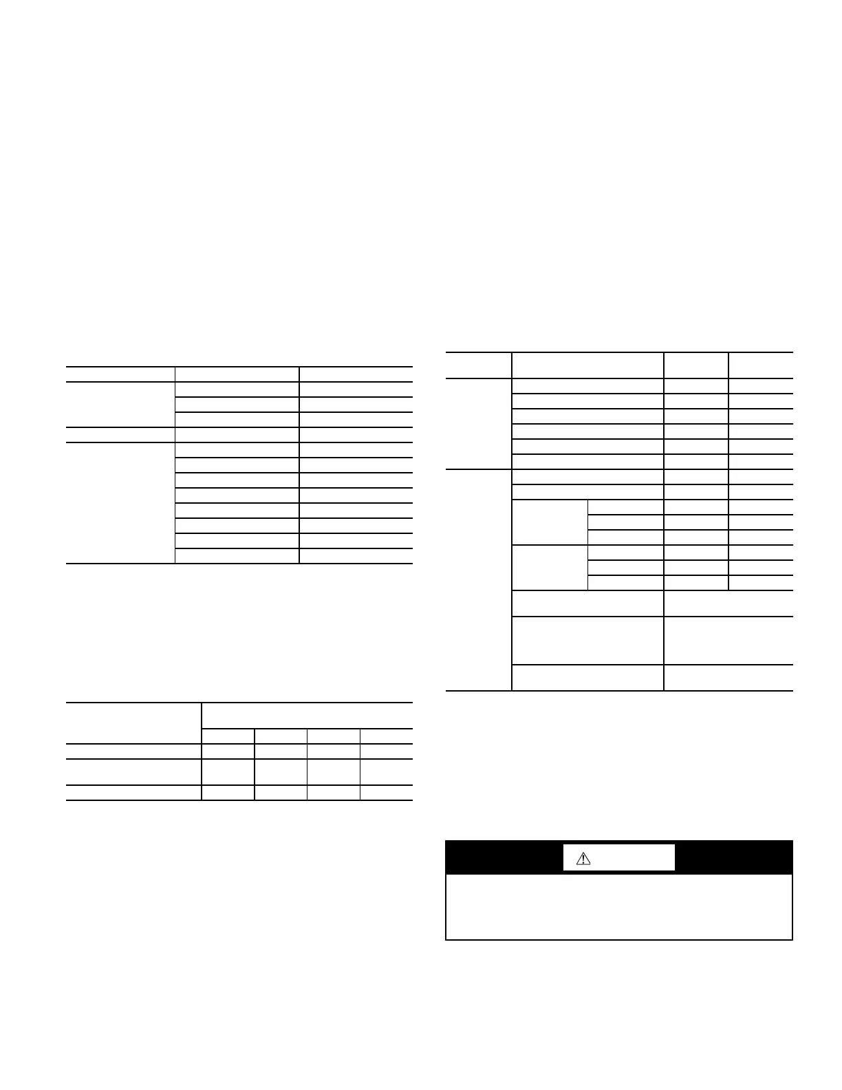
Table 19 — Approximate Fluid Volume (gal.)
per 100 Ft of Pipe
a
NOTE(S):
a. Volume of heat exchanger is approximately 1.0 gallon.
PIPE DIAMETER (in.) VOLUME (gal.)
Copper
1 4.1
1.25 6.4
1.5 9.2
Rubber Hose 1 3.9
Polyethylene
3/4 IPS SDR11 2.8
1 IPS SDR11 4.5
1-1/4 IPS SDR11 8.0
1/2 IPS SDR11 10.9
2 IPS SDR11 18.0
1-1/4 IPS SCH40 8.3
1-1/2 IPS SCH40 10.9
2 IPS SCH 40 17.0
LEGEND
IPS — Internal Pipe Size
SCH — Schedule
SDR — Standard Dimensional Ratio
Table 20 — Antifreeze Percentages by Volume
ANTIFREEZE
MINIMUM TEMPERATURE FOR
FREEZE PROTECTION (°F)
10 15 20 25
Methanol (%) 25 21 16 10
100% USP Food Grade
Propylene Glycol (%)
38 30 22 15
Ethanol (%) 29 25 20 14
Table 21 — Operating Limits
FLUID
TYPE
LIMIT COOLING HEATING
Air
Minimum Ambient (°F) 50 40
Maximum Ambient (°F) 100 85
Rated Ambient (°F) 80 68
Minimum Entering (°F db/ wb) 65/57 45
Maximum Entering (°F db/wb) 95/85 80
Rated Entering (°F) 80/67 68/57
Liquid
Minimum Entering (°F)
a
NOTE(S):
a. Units with waterside economizer options can operate with EWT < 45°F.
45 20
Max Entering (°F) 110 80
Typical
Entering
Range (°F)
Water Loop — —
Ground Loop 50-80 25-50
Ground Water 50-70 40-60
Rated
Entering (°F)
Water Loop 86 68
Ground Loop 77 32
Ground Water 59 50
Anti-Freeze Requirement
(LWT/EWT °F)
<40 / <50
Maximum operating water
pressure (PSI/kPa)
400 psi/2,758 kPa
(Standard unit)
300 psi/2,068 kPa (with
water valve option)
Minimum operating Flow Rate
(GPM/Ton)
1.5
LEGEND
DB —Dry Bulb
EWT — Entering Water Temperature
LWT — Leaving Water Temperature
WB —Wet Bulb
WARNING
When the disconnect switch is closed, high voltage is present
in some areas of the electrical panel. Exercise caution when
working with the energized equipment. Failure to heed this
warning could lead to personal injury.
Bekijk gratis de handleiding van Carrier Aquazone 50WD, stel vragen en lees de antwoorden op veelvoorkomende problemen, of gebruik onze assistent om sneller informatie in de handleiding te vinden of uitleg te krijgen over specifieke functies.
Productinformatie
| Merk | Carrier |
| Model | Aquazone 50WD |
| Categorie | Niet gecategoriseerd |
| Taal | Nederlands |
| Grootte | 15865 MB |


