Carrier Aquazone 50WD handleiding
Handleiding
Je bekijkt pagina 17 van 84
17
Water Tank Refill
1. Open the cold water supply to the tank.
2. Open a hot water faucet to vent air from the system until
water flows from the faucet, then close.
3. Depress the hot water tank pressure relief valve handle to
ensure there is no air remaining in the tank.
4. Carefully inspect all plumbing for water leaks. Correct as
required.
5. Purge all air from HWG by depressing the Schrader valve on
the HR unit. Allow all air to bleed out until water appears at
the valve.
6. Before restoring the power or fuel supply to the water heater,
adjust the temperature setting on the tank thermostat(s) to
ensure maximum utilization of heat available from the refrig-
eration system and to conserve the most energy. On tanks
with thermostats and both upper and lower elements, the
lower element should be turned down to 100°F, while the
upper element should be adjusted to 120°F. Depending upon
the specific needs of the customer, you may need to adjust the
upper element differently. On tanks with a single thermostat,
lower the thermostat setting to 120°F or the “LOW” position.
After thermostat adjustments are completed, replace access
cover and restore electrical or fuel supply to water heater.
INITIAL START-UP
1. Turn on the heat pump. The circulating pump should not run
if the compressor is not running.
2. Turn HWG switch to the “ON” position. The pump will oper-
ate if entering water temperature to HWG is below 120°F.
3. Ensure the temperature difference between the water entering
and leaving the heat recovery is 5 to 15°F.
4. Allow the unit to operate for 20 to 30 minutes to ensure it is
functioning properly. The pump should shut off when the
water temperature entering the generator reaches 120°F.
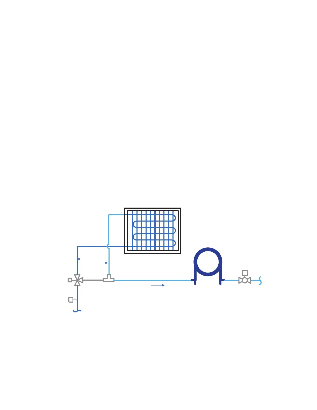
UNITS WITH WATERSIDE ECONOMIZER
The optional waterside economizer (pre-cooling coil) is factory in-
stalled and piped internally, in series with the condenser water cir-
cuit (see Fig. 18). A diverting 3-way motorized valve, entering
water temperature sensor, drain pan with condensate overflow
switch, and factory controls are included with the option.
The remote bulb (EWT sensor) is shipped internal to the unit and
requires to be installed on straight incoming water line to the unit/
3-way diverting valve (see Fig. 18). Care should be taken not to
dent the bulb or mis-calibration may occur. The remote sensing
bulb must be installed on a straight section of uninsulated pipe that
provides a good measurement of the entering water temperature. It
is recommended to insulate the sensing bulb after installation for
better water temperature sensing.
When unit is shipped with economizer option, the economizer
drain must be connected to a separate trap. Follow the same steps
for the economizer drain as described for evaporator condensate
drain Step 6 — “Install Condensate Drain” on page 14.
Refer to Step 9 — “Configure Unit Control Components” on
page 24 for Economizer configuration for units with Option Card
(units without factory installed TruVu™ controller).
Refer to the TruVu controller section of this manual for configur-
ing the entering water temperature set point for economizer opera-
tion for units with TruVu DDC controller.
See Table 1 and 2 for connection sizes. Refer to the unit’s perfor-
mance report for economizer performance and additional water
and air pressure drop.
Fig. 18 — Waterside Economizer Diagram
M
T
M
WSE Coil
Fluid IN
Fluid OUT
N.O.
N.C.
Motorized
3-Way Valve
EWT Sensor
(field-installed)
Condenser
Coil
Isolation
Valve
(optional)
Bekijk gratis de handleiding van Carrier Aquazone 50WD, stel vragen en lees de antwoorden op veelvoorkomende problemen, of gebruik onze assistent om sneller informatie in de handleiding te vinden of uitleg te krijgen over specifieke functies.
Productinformatie
| Merk | Carrier |
| Model | Aquazone 50WD |
| Categorie | Niet gecategoriseerd |
| Taal | Nederlands |
| Grootte | 15865 MB |


