Carrier 39S handleiding
Handleiding
Je bekijkt pagina 30 van 64
30
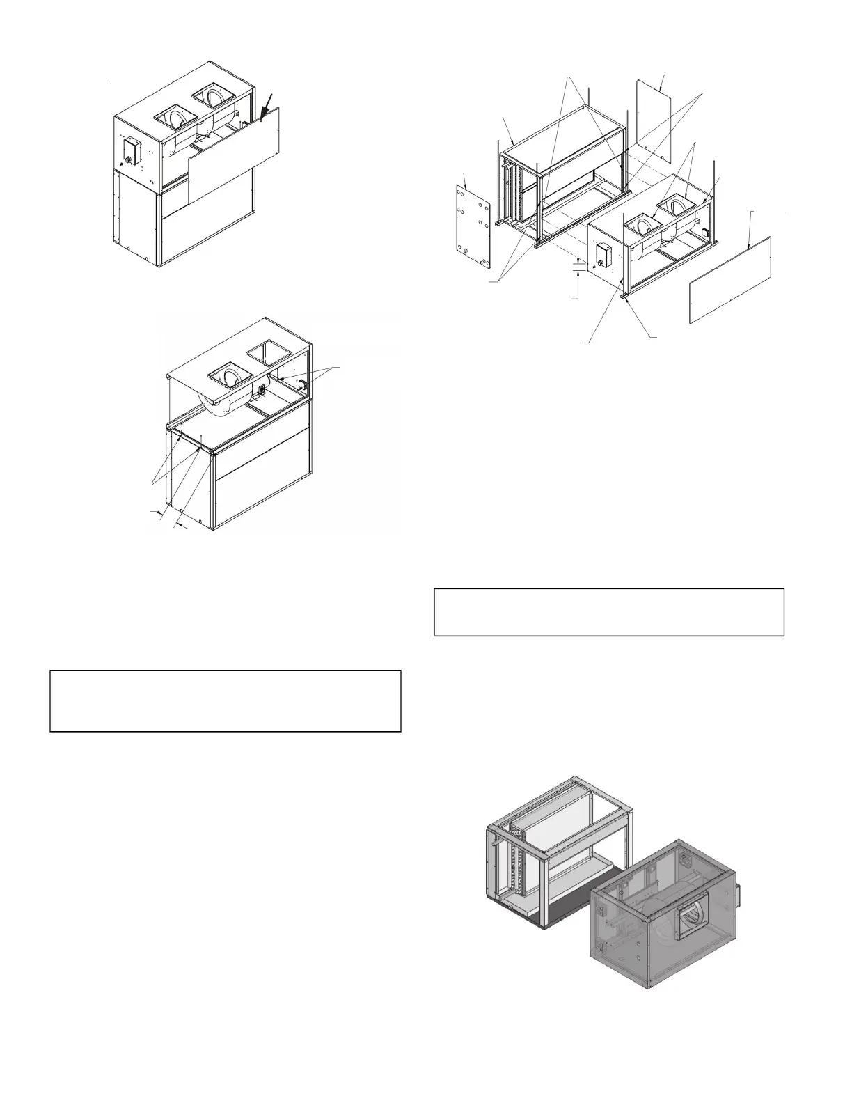
Fig. 26 — Remove Access Panel
Fig. 27 — Connect Sections with Screws
39SM Unit Sizes 07-17 (Horizontal Configurations)
1. Remove red shipping screws from duct flange/blower outlet
before assembly. See Fig. 25.
2. Use factory-provided foam gasket tape to seal the joint
between the sections.
NOTE: Gasket material is factory-provided unless the orienta-
tion of the unit is being changed from that ordered. In that case,
use field-provided gasket or factory-provided gasket kit.
3. Remove coil section side panels and blower section access
panels. See Fig. 28.
4. Align coil and blower sections in the correct orientation, as
shown in the appropriate horizontal configuration in Fig. 24.
5. Drill flanges and install 3/8-16 x 1 in. long bolts, flat washers
and locknuts as shown in Fig. 27. Unit sizes 07 and 09 require
2 bolts per side (4 total). Unit sizes 13 and 17 require 3 bolts
per side (6 total).
6. Reinstall side and access panels.
Fig. 28 — Connect Sections (Horizontal
Configurations)
39SM UNIT SIZES 07-17 VERTICAL TO HORIZONTAL
CONVERSION
Unit is shipped in one of the configurations shown in Fig. 24. It is
possible to change the configuration to another shown in Fig. 24
using the following procedure:
1. Remove the front panel by removing the panel screws.
2. Remove the 2 side panels by removing the panel screws.
3. Rotate the blower section so that the opening is aligned with
the front of the coil section. See Fig. 29. If desired, relocate
motor mounting rails, plate, and motor to alternate location
for easier service access.
4. Insert gasket kit or field-provided gasket material between the
coil section and the blower section and fasten with bolts as
required. See Fig. 29.
5. Replace the 2 side panels in their original locations.
6. Insert a suitable gasket material around the top flanged open-
ing and place what was the front panel on the top of the unit
(shaded panel in Fig. 30). Fasten with screws.
Fig. 29 — Align Blower Section Opening with
Coil Section Front
IMPORTANT: Failure to remove red shipping screws can
result in unsatisfactory vibration or blower noise, or exces-
sive air recirculation.
Access
Panel
8 in. (203.2 mm)
TYP
FROM FRONT
AND REAR
PANELS
No.10 x 3/4 in.
SELF-TAP
SCREW
(TYP)
No. 10 x 3/4 in.
SELF-TAP
SCREW
(TYP)
IMPORTANT: The final configuration must match one of the
permitted arrangements shown in Fig. 24.
Add Center Bolt (3/8 - 16 X 1 in. Hx. Hd.)
On Unit Sizes 13,17
Side
Panel
Side
Panel
Coil Section
3/8 - 16 X 1 in.
Hx. Hd. Bolts
(Unit Sizes 13,17)
3/8 - 16 X 1 In.
Hx. Hd. Bolts
(Unit Sizes 13,17)
4 in. (Typ)
From Top
and Bottom
Edges
3/8 in. (Min.) Threaded Rod
(Field-supplied)
Bottom Supports
(Field-supplied)
Blower
Access
Panel
Blower
Section
Remove Red
Shipping Screws
Bekijk gratis de handleiding van Carrier 39S, stel vragen en lees de antwoorden op veelvoorkomende problemen, of gebruik onze assistent om sneller informatie in de handleiding te vinden of uitleg te krijgen over specifieke functies.
Productinformatie
| Merk | Carrier |
| Model | 39S |
| Categorie | Niet gecategoriseerd |
| Taal | Nederlands |
| Grootte | 10967 MB |


