Carrier 39L handleiding
Handleiding
Je bekijkt pagina 48 van 76
48
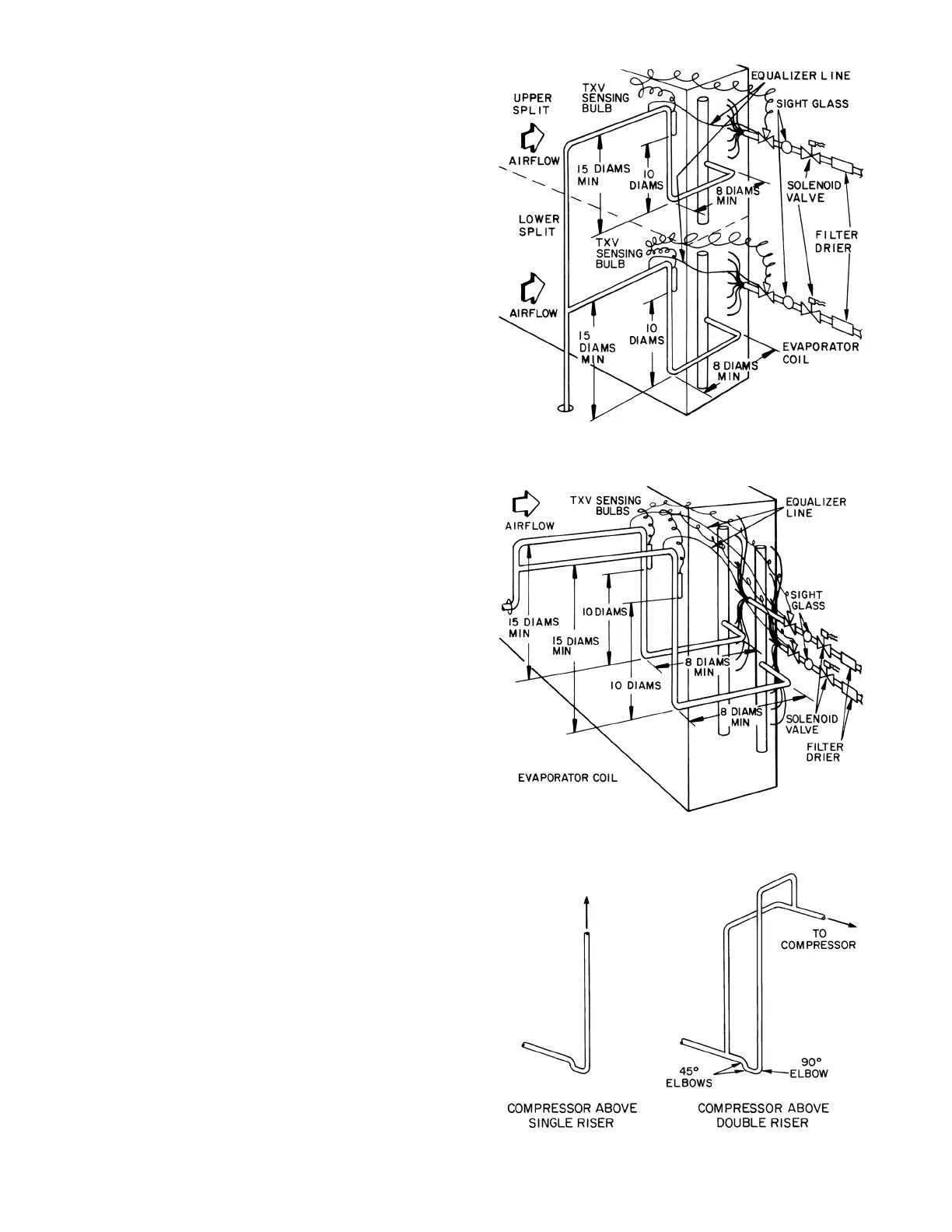
Suction line from coil connection to end of the 15-diameter-long
riser should be same tube size as coil connection to ensure proper
refrigerant velocity.
Refer to Carrier System Design Manual, Part 3, and size remain-
ing suction line to compressor for a pressure drop equivalent to
2.0°F. This will provide a total suction line header pressure drop
equivalent to approximately 2.5°F. Refer to Fig.
53 for piping ris-
ers to the compressor.
To minimize the possibility of flooded starts and compressor dam-
age during prolonged light load operation, install an accumulator
in the suction line or a solenoid in the liquid line of last-on, first off
split in row-split applications.
EXPANSION VALVE PIPING
Distributor nozzles sized for acceptable performance for a range
of conditions are factory supplied. Use the AHU (Air-Handling
Unit) selection program in the Carrier electronic catalog to select
optimal nozzle sizes. Replace factory nozzle as necessary for best
performance. See Fig.
54.
Thermostatic expansion valves are field supplied.
NOTE: Be sure that correct nozzle is installed in each distributor
before installing expansion valve. Before installing field-supplied
nozzles, remove nozzle retainer rings and factory-installed
minimum-sized nozzles from distributors.
Install expansion valve (Fig. 54) as follows:
1. Wrap wet cloths around valve body to prevent excessive heat
from reaching diaphragm and internal parts. Do not allow
water to enter system. Disassemble expansion valve before
soldering, if accessible, for easy reassembly. Use 95-5 tin-
antimony soft solder.
2. Solder expansion valve outlet directly to distributor unless:
a. An adapter bushing or coupling is supplied by the fac-
tory (solder adapter to distributor first, then to expansion
valve).
b. Hot gas bypass is required. (See Hot Gas Bypass section,
below.)
3. Solder expansion valve equalizer line to suction line and
locate control bulb on suction line as in Fig.
51 or 52.
4. Insulate expansion valve body, diaphragm assembly and con-
trol bulb area to prevent charge migration and excessive
condensation.
5. Install filter drier ahead of expansion valve to ensure satisfac-
tory valve operation.
HOT GAS BYPASS
When low-load operation requires use of hot gas bypass, hot gas
must be introduced between expansion valve and distributor. See
Table
19.
Install hot gas bypass connector (Fig. 55 and 56) in coil split that is
first on, last off as follows:
1. Remove distributor nozzle and retainer ring (area A) from
distributor and reinstall in inlet (area B) of side connector.
2. Solder side connector outlet to distributor inlet, using silver
solder or equivalent with 1300 to 1500°F melt temperature.
3. Silver-solder expansion valve outlet to side connector inlet.
4. If required, install factory-supplied adapter bushing or cou-
pling to connector inlet before soldering to expansion valve
outlet.
Fig. 51 — Face Split Coil Suction Line Piping
Fig. 52 — Row Split Coil Suction Line Piping
Fig. 53 — Suction Line Riser Piping
TXV — Thermostatic Expansion Valve
TXV — Thermostatic Expansion Valve
Bekijk gratis de handleiding van Carrier 39L, stel vragen en lees de antwoorden op veelvoorkomende problemen, of gebruik onze assistent om sneller informatie in de handleiding te vinden of uitleg te krijgen over specifieke functies.
Productinformatie
| Merk | Carrier |
| Model | 39L |
| Categorie | Niet gecategoriseerd |
| Taal | Nederlands |
| Grootte | 14640 MB |


