Carrier 39L handleiding
Handleiding
Je bekijkt pagina 41 van 76
41
NOTE: Do NOT use an immersion thermostat to override a duct
thermostat and open the steam supply valve.
For vacuum return systems, the vacuum breaking check valve
would be piped into the condensate line between the trap and the
gate valve instead of open to the atmosphere.
Figure 46 illustrates the typical piping at the end of every
steam supply main. Omitting this causes many field problems
and failed coils.
Figure 47 shows the typical field piping of multiple coils. Use
this only if the coils are the same size and have the same pres-
sure drop. If this is not the case, an individual trap must be pro-
vided for each coil.
Figure 48 shows a multiple coil arrangement applied to a gravity
return, including the open air relief to the atmosphere, which
DOES NOT replace the vacuum breakers.
Figure 49 illustrates the basic condensate lift piping.
Following the piping diagrams in Fig. 45-49, make all connections
while observing the following precautions:
• Install a drip line and trap on the pressure side of the inlet
control valve. Connect the drip line to the return line
downstream of the return line trap.
• To prevent scale or foreign matter from entering the con-
trol valve and coil, install a 3/32 in. mesh strainer in the
steam supply line upstream from the control valve.
• Provide air vents for the coils to eliminate non-condensible
gases.
• Select a control valve according to the steam load, not the
coils supply connection size. Do not use an oversized control
valve.
• Do not use bushings that reduce the size of the header return
connection. The return connection should be the same size as
the return line and reduced only at the downstream trap.
• To lift condensate above the coil return line into overhead
steam mains, or pressurized mains, install a pump and re
-
ceiver between the condensate trap and the pressurized
main. Do not try to lift condensate with modulating or on-
and-off steam control valves. Use only 15-degree check
valves, as they open with a lower water head. Do not use
45-degree or vertical-lift check valves.
• Use float and thermostatic traps. Select the trap size according
to the pressure difference between the steam supply main and
the return main.
• Load variations can be caused by uneven inlet air distribution
or temperature stratification.
• Drain condensate out of coils completely at the end of the
heating season to prevent the formation of acid.
LEGEND
NOTE: All hot water coils have 1-1/2 in. MPT.
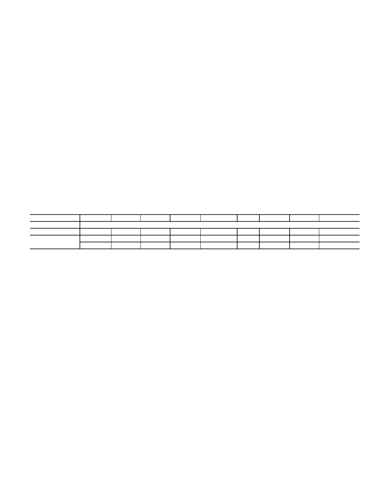
Table 14 — Hot Water Coil Circuiting Data
39L UNIT SIZE 03 06 08 10 12 15 18 21 25
No. of Circuits
1-ROW H 6 81010 10131515 13
2-ROW H
F
6 81010 10131515 13
12 16 20 20 20 26 30 30 36
F — Full Circuit
H — Half Circuit
Bekijk gratis de handleiding van Carrier 39L, stel vragen en lees de antwoorden op veelvoorkomende problemen, of gebruik onze assistent om sneller informatie in de handleiding te vinden of uitleg te krijgen over specifieke functies.
Productinformatie
| Merk | Carrier |
| Model | 39L |
| Categorie | Niet gecategoriseerd |
| Taal | Nederlands |
| Grootte | 14640 MB |


