Valcom VIP-172AL-VRSS-SA handleiding
Handleiding
Je bekijkt pagina 3 van 4
3 947839
R OO2
N/O
N/C
COM
Step 3. Connect the RJ45 cable from the network. This device is powered via
Power over Ethernet (PoE). If PoE is unavailable from the network
Step 4. Program the VIP-172AL using the VIP-102B IP Solutions Setup Tool.
Step 3
SIGNAL OUTPUT
NETWORK
NETWORK
INTERFACE
VIP-172AL
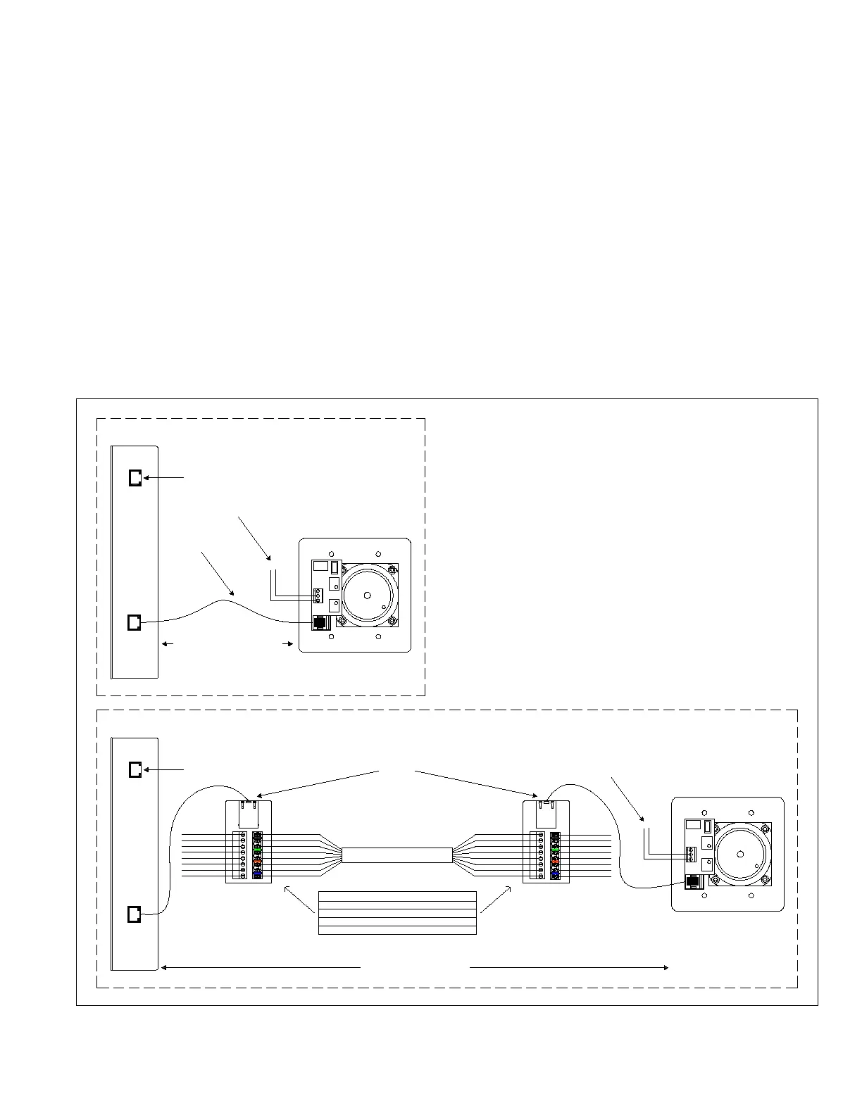
DOOR PLATE
Step 1. An optional relay output is provided for activating electric door controls,
strike plates, gates, etc. A Normally Open (NO) and Normally Closed (NC)
connection is available. Consult the door equipment manufacturer’s
documentation for connections to their device. The relay can be activated
Step 2. Connect the Door Plate to the Network Interface. If the Door Plate is close
to the Network Interface, a standard Patch Cable may be used to connect
between them (Figure A). For longer distances, the VM-186 RJ45 Junction
Boxes can be used to extend up to 350' between the Door Plate and Network
switch then an inline power injector will be required.
Step 1
Step 2
R OO2
N/O
N/C
COM
350' MAXIMUM DISTANCE
CAT 3/5/6 UTP
VIP-172AL Quick Start Installation
Step 3
VM-186 COLOR CODES - FUNCTION
ORANGE & WHITE/ORANGE - LED
GREEN & WHITE/GREEN - RELAY CONTROL
BLUE & WHITE/BLUE - CALL SWITCH
BROWN & WHITE/BROWN - AUDIO
WHITE/BLUE
BLUE
WHITE/ORANGE
ORANGE
WHITE/GREEN
GREEN
WHITE/BROWN
BROWN
WHITE/BLUE
BLUE
WHITE/ORANGE
ORANGE
WHITE/GREEN
GREEN
WHITE/BROWN
BROWN
VM-186
RJ45
BROWN
BLUE
VM-186
RJ45
BROWN
BLUE
WHITE/BLUE
WHITE/ORANGE
ORANGE
WHITE/GREEN
GREEN
WHITE/BROWN
BROWN
WHITE/BLUE
BLUE
WHITE/ORANGE
ORANGE
WHITE/GREEN
GREEN
WHITE/BROWN
BROWN
BLUE
SIGNAL OUTPUT
NETWORK
NETWORK
INTERFACE
VIP-172AL
DOOR PLATE
Step 2 Step 1
by pressing the # key on the answering telephone.
Interface (Figure B).
FIGURE A
FIGURE B
350' MAXIMUM DISTANCE
SETUP
The VIP-172AL will automatically acquire an IP
address (using DHCP) and connect to the
Revolution server when connected to the
network and powered up. Information specific to
your application will need to be programmed into
the Revolution server. Refer to the Revolution
documentation for further information.
Additional setup may be required using the
Valcom IP Solutions Setup Tool. The Setup
Tool may be downloaded from the Valcom web
site at http://www.valcom.com/vipsetuptool.
TECHNICAL ASSISTANCE
Assistance in troubleshooting is available from
the factory. Call (540) 563-2000 and press 1 for
Technical Support or via email at
support@valcom.com.
When requesting assistance, you should include
all available information. General information
and troubleshooting procedures are available on
the Valcom website at www.valcom.com.Valcom
equipment is not field repairable. Valcom, Inc.
maintains service facilities in Roanoke, VA.
Should repairs be necessary, attach a tag to the
unit clearly stating your company name,
address, phone number, contact person and the
nature of the problem.
Send the unit to:
Valcom, Inc.
Repair & Return Dept.
5614 Hollins Road
Roanoke, Va. 24019-5056
WARRANTY
Warranty information may be found on our
website at www.valcom.com/warranty
Figure 1. Quick Start Installation
Bekijk gratis de handleiding van Valcom VIP-172AL-VRSS-SA, stel vragen en lees de antwoorden op veelvoorkomende problemen, of gebruik onze assistent om sneller informatie in de handleiding te vinden of uitleg te krijgen over specifieke functies.
Productinformatie
| Merk | Valcom |
| Model | VIP-172AL-VRSS-SA |
| Categorie | Niet gecategoriseerd |
| Taal | Nederlands |
| Grootte | 635 MB |


