Supermicro X14SBH-AP handleiding
Handleiding
Je bekijkt pagina 53 van 140
Fan Headers
There are seven 6-pin fan headers (FAN1–FAN7) and three 4-pin fan headers (FAN8–FAN10)
on the X14SBH-AP motherboard. All the 4-pin fan headers are backwards compatible with the
traditional 3-pin fans. However, fan speed control is available for all fans except FAN9 by
Thermal Management via the IPMI 2.0 interface.
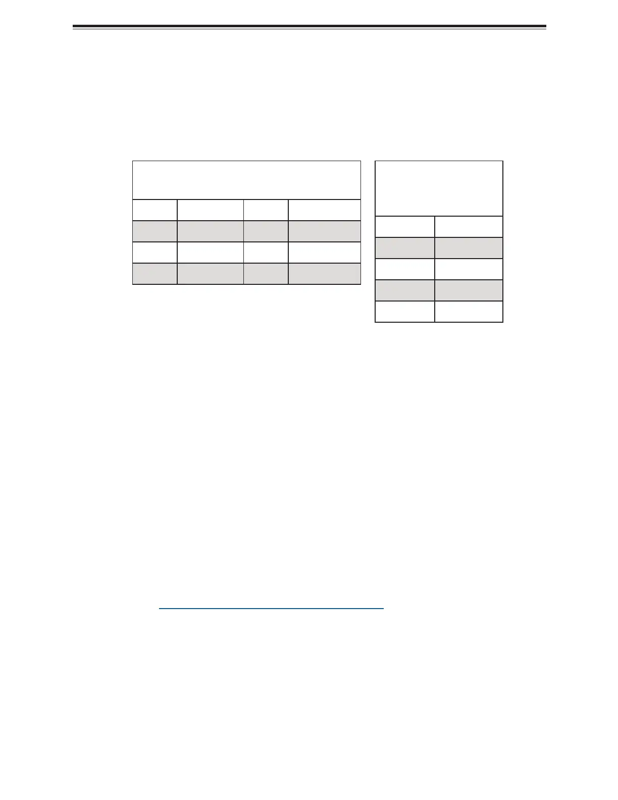
6-pin Fan Header
Pin Definitions: Six Total
Pin# Definition Pin# Definition
1 GND 4 +12 V
2 +12 V 5 Tachometer
3 GND 6 PWM
4-pin Fan Header
Pin Definitions: Four
Total
Pin# Definition
1 GND (Black)
2 +12 V (Red)
3 Tachometer
4 PWM Control
M.2 M-Key PCIe 5.0 p53-x2 Slots
Two M.2 M-key slots are located at M.2-C1 and M.2-C2 on the X14SBH-AP motherboard. The
M.2 M-key slots on the motherboard support PCIe 5.0 p53-x2 devices in a 25110/2280/22110 form
factor.
For a detailed diagram of the X14SBH- AP motherboard, see the layout under "Quick
Reference" on page 12.
NC-SI Connection
The Network Controller Sideband Interface (NC-SI) connection is located at JNCSI1 on the
X14SBH-AP motherboard. This connection is used to connect a Network Interface Card (NIC)
to the motherboard to allow the onboard Baseboard Management Controller (BMC) to
communicate with a network.
Note: For detailed instructions on how to configure Network Interface Card (NIC) settings,
refer to the Network Interface Card Configuration User's Guide posted on the web page
under the link: https://www.supermicro.com/support/manuals.
For a detailed diagram of the X14SBH- AP motherboard, see the layout under "Quick
Reference" on page 12.
53
X14SBH-AP: Component Installation
Bekijk gratis de handleiding van Supermicro X14SBH-AP, stel vragen en lees de antwoorden op veelvoorkomende problemen, of gebruik onze assistent om sneller informatie in de handleiding te vinden of uitleg te krijgen over specifieke functies.
Productinformatie
| Merk | Supermicro |
| Model | X14SBH-AP |
| Categorie | Niet gecategoriseerd |
| Taal | Nederlands |
| Grootte | 17647 MB |


