Supermicro H14DSG-OD handleiding
Handleiding
Je bekijkt pagina 44 van 113
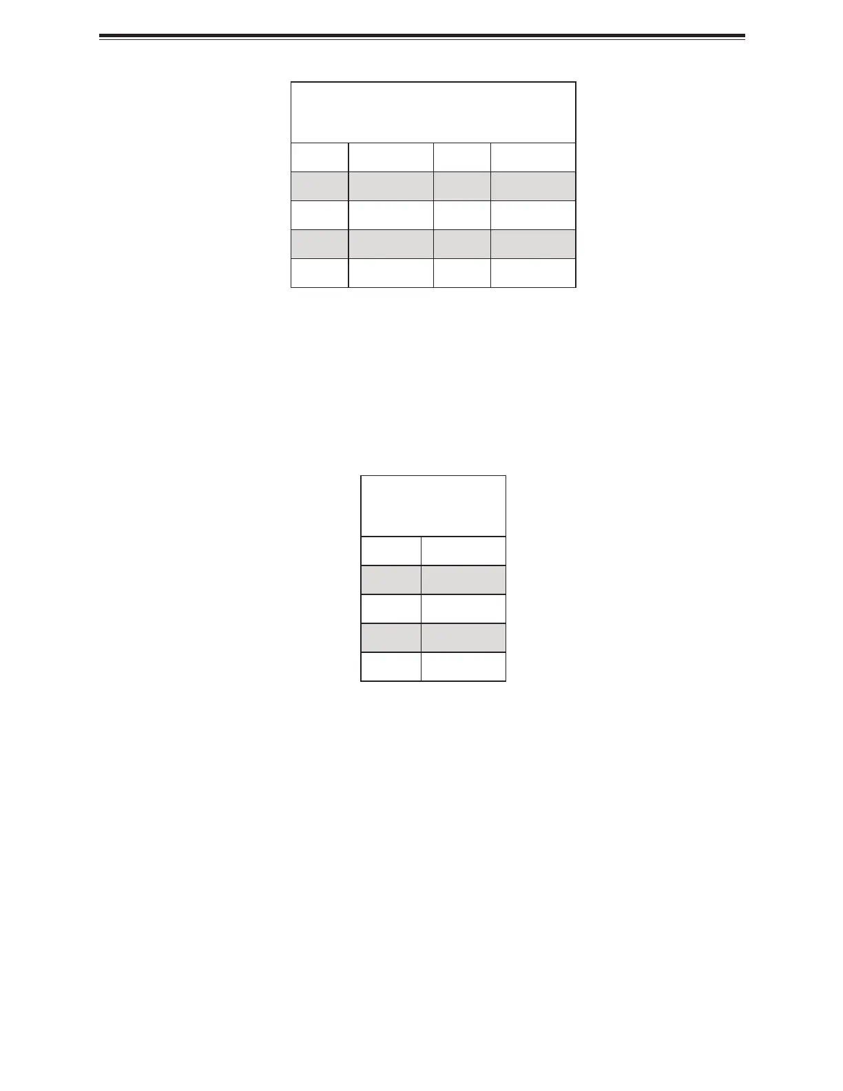
8-Pin Power
Pin Definitions
Pin# Definition Pin# Definition
1 Ground 5 +12 V
2 Ground 6 +12 V
3 Ground 7 +12 V
4 Ground 8 +12 V
E1.S Backplane, M.2 Module, BlueField-3 Risers, and BlueField-3
Bridge Boards 12 V 4-pin Power Connectors
JPWR11, JPWR13, JPWR14, and JPWR15 are 4-pin 12 VDC power inputs. JPWR11 provides
power to the system's E1.S backplane. JPWR13 supplies power to the system's M.2 module.
JPWR14 is used for the system's left BlueField-3 riser and BlueField-3 bridge board via a Y
cable. JPWR15 powers the system's right BlueField-3 riser and BlueField-3 bridge board, also
through a Y cable. Refer to the table below for pin definitions.
4-Pin Power
Pin Definitions
Pin# Definition
1 Ground
2 Ground
3 12 V
4 12 V
Headers and Connections
For information about the headers of the H14DSG-OD motherboard, refer to the following
content.
Fan Headers (FAN1 to FAN5)
There are five fan headers (FAN1 to FAN5) on the motherboard. These are 6-pin fan headers,
with pins 1-3 being backward compatible with traditional 3-pin fans. The onboard fan speeds
are controlled by Fan Mode in the BMC. When using Fan Mode setting, use all 6-pin fans.
44
H14DSG-OD: Component Installation
Bekijk gratis de handleiding van Supermicro H14DSG-OD, stel vragen en lees de antwoorden op veelvoorkomende problemen, of gebruik onze assistent om sneller informatie in de handleiding te vinden of uitleg te krijgen over specifieke functies.
Productinformatie
| Merk | Supermicro |
| Model | H14DSG-OD |
| Categorie | Niet gecategoriseerd |
| Taal | Nederlands |
| Grootte | 16495 MB |


