Supermicro H14DSG-OD handleiding
Handleiding
Je bekijkt pagina 43 van 113
2.6 Connections, Jumpers, and LEDs
Refer to the following sections for information about connections, jumpers, and LEDs for the
H14DSG-OD motherboard.
Power Supply Connections
For information about the power connections of the H14DSG-OD motherboard, refer to the
following content.
Power Supply
As with all computer products, a stable power source is necessary for proper and reliable
operation. It is even more important for processors that have high CPU clock rates where noisy
power transmission is present.
Power Supply Connectors
The H14DSG-OD has four PowerMAX power input connectors: JSW_PWR1, JSW_PWR2,
and JSW_PWR4 for 12 VDC power input via the midplane, and JSW_P54V1 for 54 VDC power
input via the midplane.
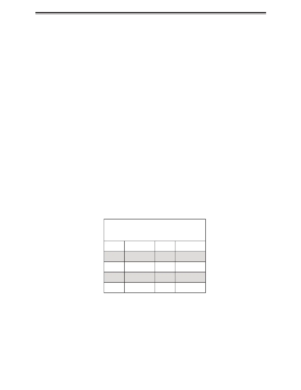
Fan Board 54 V 8-pin Connector
JPWR6 is an 8-pin, 54 VDC power connector for the system's fan board. Refer to the table
below for pin definitions.
Fan Board Power
Pin Definitions
Pin# Definition Pin# Definition
1 Ground 5 +54 V
2 Ground 6 +54 V
3 Ground 7 +54 V
4 Ground 8 +54 V
Backplane and BlueField-3 Card 12 V 8-pin Power Connectors
JPWR3, JPWR4, and JPWR12 are 8-pin 12 VDC power inputs. JPWR3 and JPWR4 are for the
system's left and right BlueField-3 cards. JPWR12 is for the system’s backplane. Refer to the
table below for pin definitions.
43
H14DSG-OD: Component Installation
Bekijk gratis de handleiding van Supermicro H14DSG-OD, stel vragen en lees de antwoorden op veelvoorkomende problemen, of gebruik onze assistent om sneller informatie in de handleiding te vinden of uitleg te krijgen over specifieke functies.
Productinformatie
| Merk | Supermicro |
| Model | H14DSG-OD |
| Categorie | Niet gecategoriseerd |
| Taal | Nederlands |
| Grootte | 16495 MB |


