Steinberg SBS-THE-600 handleiding
Handleiding
Je bekijkt pagina 21 van 49
40 41
Rev. 22.02.2022
Rev. 22.02.2022
2. BS ANGLE
A. Press 2.BACKSIGHT and 2.BS ANGLE in the „Data
Collect“ menu (g. b), input the angle from K3 to K2:
300 ° 01‘33 „(g. c). Press F4 ENT to conrm and go
to the next page (g. d).
B. Aim at the center of the K2 target, press F4 YES to set
the horizontal angle as the backsight angle (g. e).
Press F4 YES to conrm the angle (g. f) then press
F4 REC to start distance measurement (g. g).
8.4. FS / SS
Measure and store the coordinates of detail points through
the last occupied point and the backsight point.
A. Press 3.FS / SS in the „data collect“ menu (g. a),
press F1 INPUT to input the point name, code and
target hight (R.HT), press F4 ENT to conrm (g. c).
B. Press F3 MEAS and F3 NEZ to measure the distance,
an example is shown in gure e.
C. Press F4 YES to save the data to the current le and
return to the FS / SS page (g. f).
D. The point name will increase automatically, e.g. from
1 to 2. Complete the measurement of the four points
based on the previous steps.
After measuring 4 detail points, press ESC and return to the
„Data Collect“ menu.
A. Press 3.FS / SS (g. b) and F2 VIEW to enter the point
list (g. b). Move the cursor to point 1 (g. c) and
press F1 VIEW to select the coordinates (g. d). Press
F4 P1 ↓ to go to the next page (g. e).
B. Press ▼ repeatedly to check the coordinate from
point 2 to point 4 (g. f-h).
8.5. RESECTION
Set the instrument on an unknown point, calculate the
occupancy by measuring the azimuth or distance through
several known points. Please see chapter 6.4 for details.
8.6. „DATA COLLECT“ CONFIGURATION
Press 1.Cong on page 2 of the Data Collect menu.
8.6.1. SEQUENCE
Press 1.Collect Seq on the Cong page to set up the
sequence. The default setting is „EDIT → MEAS“.
A. EDIT → MEAS: Set point name, code and target
height before measuring points.
B. MEAS → EDIT: Measure points before editing point
name, code and target height.
8.6.2. DATA VALIDATION
Press 2.Data Conrm on the Cong page to enable or
disable the data conrmation function. The default setting
is ON.
A. ON: After measuring the points, the system will
remind you to conrm that data has been saved.
B. OFF: After measuring the points, the device will
automatically save the data without the need for user
conrmation.
8.6.3. SD / HD SELECTION
On the Cong page, press 3. Select SD / HD, the default
is SD&HD
A. SD&HD: The data will be displayed in the order of
SD&HD.
B. HD&VD: The data will be displayed in the order of
HD&VD.
9. MEMORY MANAGEMENT
The rst page of the menu will show „Memory MGR“, press
3. to enter the management mode.
Press 1.File Maintain in the „Memory MGR“ page.
9.1. MEASUREMENT FILES
Press 1.MEAS.FILE on the „File Maintain“ page, the cursor
will remain on the line of the current le. Press F4 to go
to the next page. Press ENT to display the point list of the
selected le.
Move the cursor to point 1 (g. d), press F1 VIEW to check
the coordinate data of point 1 (g. e). Press F4 to go to the
next page (g. f). The horizontal angle is the azimuth from
station to point 1; press ▼ to go to the next step (g. g).
8.3.2. SETTING BACKSIGHT POINT
Based on the previous instructions, after setting the
occupied point you can input or recall the known point as
a backsight point. If the reference point is unknown, only
the backsight direction is available, or if there are some
doubts about the changes, perform the reference point
setting separately.
1. BS COORD
A. Press 2.BACKSIGHT and 1.BS COORD in the „Data
Collect“ menu (g. b), the screen will show the latest
backsight point (g. c). Press F4 ENT to conrm. The
device will calculate the angle from the occupied
point K3 to the backsight point K2.
B. Aim at the center of K2. Press F4 YES to set (g. d).
The device will ask if it is necessary to check the
backsight point. Press F3 NO (g. e) and return to
the „Data collection“ menu.
1. NEW: Press NEW to start a new le, the system will
create two les, „SMD“ and „SCD“. „SCD“. The „SMD“
is for the measurement data and „SCD“ is for the
coordinate data.
2. IMP: Press IMP to import the „SCD“ coordinate le
into the device.
3. EXP: Press EXP to export the „TXT“, „DAT“, „CSV“ and
„DXF“ les.
4. ATTR: Press ATTR on the second page to display the
attributes of the current le including the name, size,
amount of data, creation time and date.
5. RENAME: Press RENAME on the second page to
rename the selected le.
6. DEL: Press DEL on the second page to delete the
selected le. Note that the „SMD“ and „SCD“ les will
be deleted at the same time.
9.2. COORDINATE FILES
Press 2.COORD.FILE to enter the le list. The description
of functions is the same as in chapter 9.1. „Measurement
les“.
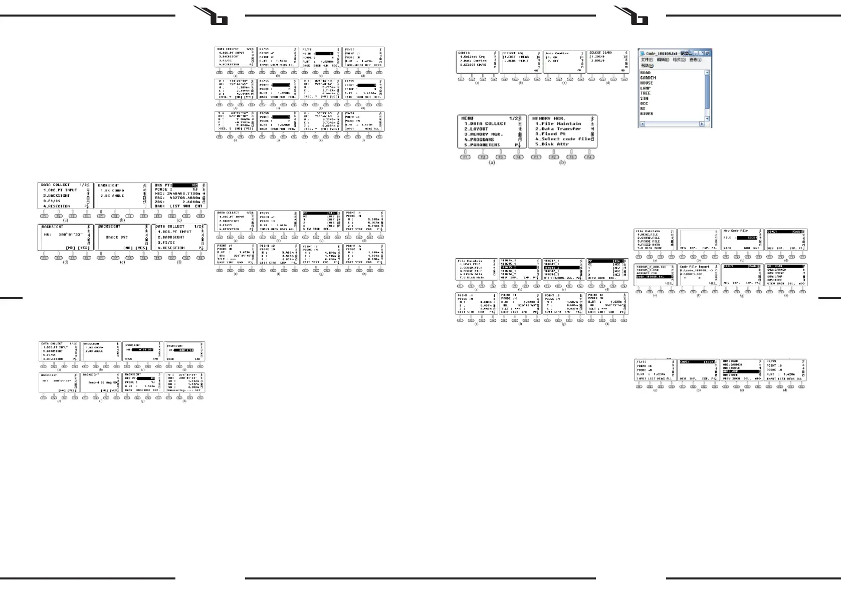
9.3. PCODE FILES
Before the measurement, you can create a TXT le on a PC
for code editing, each code appears on a separate line
within 10 characters. Copy the TXT le to the device as
shown in the gure below:
Press 3.PCODE FILE in the „File Maintain“ menu (g. b).
Press F1 NEW and input the code name „CODE1“ (g. c).
Press ENT and go back to the le list (g. d). Press F2 IMP to
display the le list, move the cursor to the desired le (g.
e). Press ENT to import the code le into CODE1. The device
will return to the le list automatically (g. g). Press ENT to
display the codes (g. h).
In the code list, press F1VIEW and F1 EDIT to edit the
selected code. Press F3 DEL and F4 OK to delete the
selected code. Press F4 ADD to add the newly created code
to the end of the le list.
Example: press 3.FS / SS in the „Data Collect“ menu (g.
a), the name of the point is 6. For the sake of the example,
assume that the code for this point is a street lamp: Move
the cursor to the code line, press F2 LIST for the requested
code le (g. b) and press ENT to select. Move the cursor
to „004: LAMP“ (g. c) and press ENT to conrm. The LAMP
code has been successfully used for point 6.
9.4. FIXED DATA
Press 4.FIXED DATA in the „File Maintain“ menu (g. b)
to enter the list of coordinate les. The le name is FIX.
LIB and it cannot be edited; the number is the number of
coordinates.
Press F4 EDIT or ENT to display the list of known points.
A) Press F1 VIEW to check the coordinates of the rst
known point (g. d), press ▲ or F3 END to check
the last point (g. e). Press F2 STRT to check the rst
point (g. h); Press F1 EDIT to edit the selected point.
B) Press F3 DEL and F4 OK to delete the selected point.
C) Press F4 ADD to manually add a new occupied point
but the point name should be dierent from the
existing points.
EN EN
Bekijk gratis de handleiding van Steinberg SBS-THE-600, stel vragen en lees de antwoorden op veelvoorkomende problemen, of gebruik onze assistent om sneller informatie in de handleiding te vinden of uitleg te krijgen over specifieke functies.
Productinformatie
| Merk | Steinberg |
| Model | SBS-THE-600 |
| Categorie | Niet gecategoriseerd |
| Taal | Nederlands |
| Grootte | 19988 MB |


