Steinberg SBS-THE-600 handleiding
Handleiding
Je bekijkt pagina 20 van 49
38 39
Rev. 22.02.2022
Rev. 22.02.2022
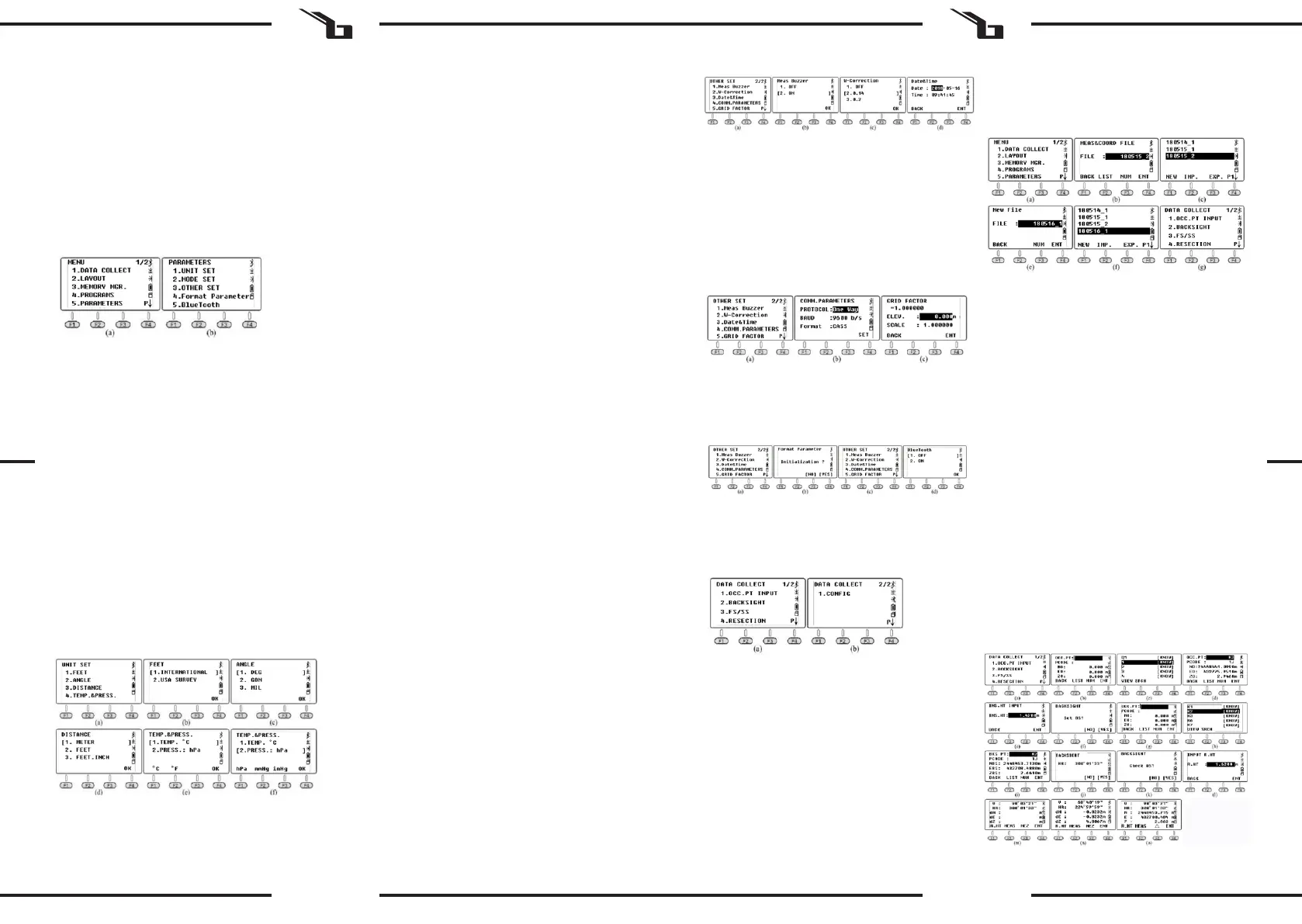
7.3.1. UNIT SETTINGS
7.3.1.1. Feet
In the unit set mode, press 1.FEET to select between
international and US feet.
* 1 international foot = 0.999,845 6 US foot.
7.3.1.2. ANGLE
In the unit set mode, press 2.Angle to select the angle unit
from DEG (degree), GON (gon), and MIL (mile). The DEG
unit is selected by default.
* 360 DEG = 400 GON = 6400MIL.
7.3.1.3. DISTANCE
In the unit set mode, press 3.Distance to select the distance
unit from meter, foot and inch.
* 1 meter = 3.280839895 feet, 1 foot = 12 inches.
7.3.1.4. TEMPERATURE AND PRESSURE
In the unit set mode, press 4.Temp. & Press to select the
temperature and pressure unit.
Temperature: With the cursor on the 1st line, press F1°C or
F2°F then press F4 OK to conrm.
* °C is selected by default
Pressure: With the cursor on the second line, press F1 hPA,
F2 mmHg, F3 inHg, then press F4 OK to conrm.
* The hPa value is selected by default.
7.3.2. OTHER SETTINGS
7.3.2.1. MINIMUM ANGLE READING
On the rst page, press 5. Parameters and 3. Other Set,
press 1.Min.Angle Read to set the minimum angle reading.
Press 1/2/3/4 to select 1s / 5s / 10s / 0.1s. The default
setting is 1s.
7.3.2.2. MINIMUM DISTANCE READING
On the rst page, press 5. Parameters and 3. Other Set,
press 2.Min.Dist Read to set the minimum distance reading .
Press 1/2 to select 1mm or 0.1mm. The default setting is
1mm.
7.3.2.3. LEFT OR RIGHT DIRECTION
Press 1.Dier to maintain unequal coordinates between
the HL / HR directions. Press 2.Equation to keep equal
coordinates regardless of the direction of HL and HR. The
default setting is Equation.
If the instrument has been set to „Equation“, when
measuring HR the system will use HR ± 180 ° as the azimuth
angle to calculate the coordinates. If the instrument has
been set to „Dier“ in HR measurement, the system will use
the actual direction as the azimuth angle. In other words,
the dierence between the two modes is 180°, which is the
azimuth angle from the occupied point to the target.
7.3.2.4. AUTOMATIC POWER OFF
Press 1/2 to turn the auto power o function to OFF or
ON. If „ON“ is selected to enable the function, the unit
will automatically turn o after 30 minutes without any
operation. The default setting is OFF.
7.3.2.5. H
-
ANGLE BUZZER
Press 1/2 to turn the horizontal angle buzzer function to
OFF or ON . When the angle h is in the range of 0 ° ± 4 ° 30
‚, 90 ° ± 4 ° 30‘, 180 ° ± 4 ° 30 ‚, 270 ° ± 4 ° 30‘, the device
activates the buzzer. The default setting is OFF.
7.3.2.6. Measurement buzzer
Press 1/2 to turn the measurement buzzer OFF / ON. The
buzzer signals a multiple angle. The device will sound the
buzzer each time a measurement is completed. The default
setting is ON.
7.3.2.7. W
-
CORRECTION
Press 1.OFF to disable W-correction. This will set the
W-correction to k = 0; Press 2.0.14 to set the W-correction
to k = 0.14; Press 3.0.2 to set the W-correction to k = 0.2.
The default value is 0.14.
* k is the coecient of earth curvature and atmospheric
vertical refraction, also known as the W-correction.
7.3.2.8. DATE AND TIME
Enter the current date and time with the numeric keys. Press
OK to conrm. The total station‘s internal clock is supported
by a battery located on the main board. The date and time
entered will not disappear even after the device is turned
o. Only when the device is not used for a long time, the
battery on the motherboard will run out and the data will
be lost. The LB-01 battery will automatically charge the
motherboard as long as the device is turned on for 3-4
hours.
7.3.2.9. COMMUNICATION PARAMETERS
On the „Comm Parameters“ page, set the protocol, baud
rate and format. Press ▲ / ▼ to move the cursor. Press ◄ /
► to select an option.
1. Protocol: Unidirectional, Ack / Nak
2. Baud: 1200/2400/4800/9600/19200/3
400/57600/115200
3. Format
* The baud rate is only available for the RS-232C
connection. Not applicable to USB and Bluetooth ports.
7.3.2.10. GRID FACTOR
The default value of the grid factor is μ = 1.
7.2.2. INFORMATION
Press 3. Information in the 2nd menu page (g. b).
1. MB: 03/20180126 - Motherboard 03, updated on
January 26, 2018.
2. EDM: 05/20161110 - EDM 05, updated on November
10, 2016.
3. CCDV: 19/20160629 - Horizontal disc 19, updated on
June 29, 2016.
4. CCDH: 19/20160629 - Vertical disc 19, updated on
June 29, 2016.
5. TILT: 01/20131015 - Tilt 01, updated on November
10, 2016.
7.3. PARAMETERS
Press 5. Parameter in the 1st menu page.
7.3.3. FORMAT PARAMETER
Press 4.Format Parameter to return to the initial settings.
7.3.4. BLUETOOTH
Press 1/2 to turn the Bluetooth OFF / ON. The default
setting is OFF.
8. COLLECTION, STORAGE AND SHARING OF DATA
8.1. COLLECTING DATA
The „Data Collect“ option on the rst page of the menu
is used to measure 3D coordinates and save them in the
current coordinate le and to save the observation data in
the current measurement le.
8.2. NEW JOB
Press 1.Data Collect on the rst page of the menu, enter
the le selection page, the device will display the latest le
name.
Press F2 LIST and F1 NEW to start a new job. The system will
name the new job as „Data_Num“. Press F4 ENT to conrm.
Move the cursor to a new job and press ENT to set the new
le as the current job.
1) In the le selection menu (g. b), you can also input
a new name using the number key and pressing
ENT to conrm. The system will automatically create
a new job.
2) Press 3.FS / SS to measure angle, distance and
coordinates within the current le.
3) In 1.OCC. PT INPUT or 2.BACKSIGHT you can use
a known point from existing les as an occupied
point or a backsight point.
4) N6 adds the x.lib le in the device‘s internal
memory as a le of known coordinates. You can
press 3.MEMORY MGR in the menu page, then 1.File
Maintain, 4.FIXED DATA and F2 IMP to import the
coordinates of an occupied point into the instrument.
8.3. SETTING AN OCC POINT AND BS POINT
It is assumed that the user has already imported the
coordinates into the FIX.LIB le. (A detailed description of
the steps is presented in chapter 6.1)
8.3.1. SETTING AN OCCUPIED POINT
Press 1. OCC.PT INPUT in the „Data Collect“ menu (g. a),
the last occupied point will be displayed on the screen
(picture b is the default).
A. Press F2 LIST to enter the list of points (g. c), move
the cursor to the known point K3, press ENT to
display the coordinates of K3 (g. d), press F4 ENT.
B. Input the instrument height (g. s) and press F4 ENT
to conrm. The device will go to the backsight angle
adjustment page (g. f). Press F4 YES. The newest
backsight point will be displayed (g. g shows the
default setting)
C. Press F2 LIST to enter the list of points, move the
cursor to the known point K2 (g. h), press ENT to
select and F4 ENT to conrm, the device will calculate
the angle from K3 to K2 (g. I)
D. Aim at the center of the backsight point, press F4 YES
for orientation (g. j).
E. Input the target height and press F4 YES to conrm
(g. l).
F. Press F2 MEAS to start distance measurement (g.
m), the device will show the dierence (g. n).
G. Press F3 CORD to switch to the real time coordinates
of the backsight point (g. o).
H. Press F3 to go back to the coordinate dierence
page. Press F4. to conrm.
EN EN
Bekijk gratis de handleiding van Steinberg SBS-THE-600, stel vragen en lees de antwoorden op veelvoorkomende problemen, of gebruik onze assistent om sneller informatie in de handleiding te vinden of uitleg te krijgen over specifieke functies.
Productinformatie
| Merk | Steinberg |
| Model | SBS-THE-600 |
| Categorie | Niet gecategoriseerd |
| Taal | Nederlands |
| Grootte | 19988 MB |


