Steinberg SBS-THE-600 handleiding
Handleiding
Je bekijkt pagina 18 van 49
34 35
Rev. 22.02.2022
Rev. 22.02.2022
F2 S.O .:
Stake out SD / VD / HD easily with the stakeout menu of
N6.
a) Input the stakeout value 2.0m, press F4 ENT to
conrm.
b) Turn the instrument to make sure the HR reading
matches the HR stakeout reading.
c) Ask to shift the layout prism to the eld of view. Aim
at the layout prism and press F2 MEAS, the result will
show as in gure (e).
d) dHD = actual HD - stakeout HD = -6.8265m. This
means that the layout prism should move away from
the equipment by 6.8265 m. After shifting, press F2
MEAS to conrm.
F3 FILE:
The operating instructions for this menu are the same as
those for the angle measurement mode. Users can freely
change the current le, create new les, rename, delete or
export them.
NOTE: When opening les by „txt“, there are some
dierences between 600.txt and .dat.
Edit the stakeout prole on PC: input the requested
coordinates for points 1/2/3/4, save them as “4points.csv”.
F3 FILE / P3:
Listing les or creating a new le:
Press F3 FILE, F2 LIST and F1 NEW to create a new job (g.
c). Dene the end of the prole name as FYD (g. d) Press
F4 ENT to conrm.
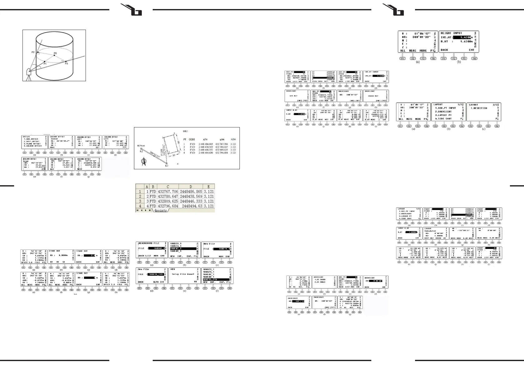
F3 OCC, OCCUPIED POINT / P2:
Press F3 OCC to enter the occupied point setting page (g.
a); it will show the coordinates of the last occupied point.
Press F2 LIST to enter the list of points (g. b).
The list of points will show the point from the known le
followed by the subsequent point from the current le.
Move the cursor to K3 and press ENT. Details of that point
will be displayed, including the codes and coordinates.
Press F4 ENT and input the instrument height, press F4 ENT
again to enter the backsight measurement setup page (g.
e). Press F4 YES to display the last backsight point (g. f).
(P1) is the point of intersection of the line (P0) and the arc,
while (P2) and (P3) are the left and right end points of the
cylindrical diameter. The device will automatically calculate
the 3D coordinates of the point P.
a) Aim at the point (P1) and press F1 MEAS (g. c). Aim
at the point (P2) and press F4 SET. Aim at the point
(P3) and press F4 SET. (g. f).
b) Press CORD to check the coordinates of the point
(P0) and press DIST to check the distance (g g).
c) Then press F1 NEXT to proceed.
6. MEASUREMENT OF COORDINATES
When the current mode is Angle or Distance measurement
mode, press CORD to enter the coordinate measurement
mode. The user can input the coordinates of the occupied
point in the standard CASS format: „Point name; Code; E, N,
Z“. You can input up to 200 points.
6.1. FUNCTION KEYS
In this coordinate menu, users can measure or stake out
points. Select or create a new prole to save coordinates,
set an occupied point and the back sight, input instrument
height and target height. In this chapter we will not
introduce the function keys according to the page order.
The following building will serve as an example to describe
the steps in the stakeout menu. The coordinates of the
occupied points K1 / K2 / K3, as shown in the gure, have
been imported into the device. Assume that the equipment
is settled at K3, while K2 is the back-sight point. The project
is to dene the location of the stakeout points 1/2/3/4 in
the eld.
This point should be the same as the point previously set.
Press F4 ENT to access the page shown in gure g.
The HR horizontal reading should be equal to the
azimuth from K3 to K2 which can be calculated from the
K3 occupancy point and the K2 backsight point. Turn the
instrument, aim at the K2 prism, press F4 YES to set the
horizontal angle equal to the azimuth from point K3 to
point K2 (g. h).
To check the back point coordinates press F3 YES, input
the prism height at the backsight point and press F3 ENT
(g. k). The device will check and calculate the dierence
between the known point (K3) and the points measured
during the control measurement of the backsight point.
Press F3 NEZ to switch the screen to display the 3D
coordinates for the measured points. Press F3 () to switch
the screen to display the coordinates dierence.
F2 B.S, BACKSIGHT / P2:
Use the backsight coordinate or angle to set the horizontal
reading of the backsight direction.
When the „OCC“ command is running, the equipment will
set the coordinate of the occupied point and the horizontal
reading of the backsight point in the same time. If there is
any doubt about the backsight direction, please rerun the
“BS” command.
To set a back-sight point, press F2 B.S. on the second page
in the coordinates menu (g. a). There are two methods:
a) Press 1 (backsight by coordinate) to enter the
backsight menu. Press F2 LIST to recall an existing
point. The method of operation is the same as for
occupied point setting.
b) Press 2 (back sight by angle). Input 300.1.33 to dene
the backsight angle of 300° 1‘33 „(g. e). Press F4
ENT to go to the next step.
c) Turn the instrument to aim at the K2 target. Press
F4 YES to set the horizontal reading matching the
direction from the occupied point K3 → B.S. point K2.
Then return to the coordinates menu.
F1 HT, Instrument Height and Target Height / P2:
To display or set the instrument height or target height,
go to page 2 of the function menu in the coordinate
measurement mode and press F1.
If no changes need to be made, press ESC to go to the
last page.
F2 S.O, Stakeout / P3:
Press F2 S.O. to access the stakeout function. On page 1/2
(g. b), point 1.OCC. PT INPUT and point 2. BACKSIGHT
are the same as the OCC and B.S. menu in the coordinate
measurement mode. Therefore, in the next part of the
Manual, point 3.Layout PT is described in detail and how to
set the stakeout point directly.
a) In the menu, on page 1/2, press 3.LAYOUT PT to enter
the stakeout function.
b) Press F2LIST to display the list of points. The cursor
will stay on the rst page automatically. Press ENT
to check the detailed coordinate (g. d); Press F4
ENT and input the target height, press F4 again to
conrm. The device will show HR and HD between
station K3 and point 1 (g. f).
c) Press F3 GUIDE to display HD and the desired
azimuth (g. g). Turn the instrument until the value
is close to 0° 00‘00 „(g. h).
d) Bring the prism to the stakeout point, aim at the
center and press MEAS to conrm the position (g. i).
e) Press the NEXT button to repeat the steps until
completion of the stakeout.
As shown in the gure below, set the current prism point as
1 ‚. To accurately set the prism to position 1, the user should
ask the persons on the side of the prism, who dene the
position 1m after the prism point 1 ‚, to conrm the azimuth
point 1 „. After measuring with tape from 1‘ to 1“, set the
prism to the position 0.732m.
Aim at the prism center, press F1 MEAS as shown in dwg. k.
At this moment, the horizontal position of the prism is the
required position for point 1. Mark this position to nish
staking out point 1. Press F4 NEXT to recall the stakeout
coordinates of point 2 (g. i).
EN EN
Bekijk gratis de handleiding van Steinberg SBS-THE-600, stel vragen en lees de antwoorden op veelvoorkomende problemen, of gebruik onze assistent om sneller informatie in de handleiding te vinden of uitleg te krijgen over specifieke functies.
Productinformatie
| Merk | Steinberg |
| Model | SBS-THE-600 |
| Categorie | Niet gecategoriseerd |
| Taal | Nederlands |
| Grootte | 19988 MB |


