Steinberg SBS-THE-600 handleiding
Handleiding
Je bekijkt pagina 16 van 49
30 31
Rev. 22.02.2022
Rev. 22.02.2022
• Turn the instrument by 90° (100 gon) around the
vertical axis and bring the level bubble to the top by
adjusting the C leveling screw.
• CAUTION! Repeat the above two steps (from step
D) after each turning of the instrument by 90 ° (100
gon). Check that the tubular level bubble is at the top
in all 4 positions.
1. Centering with the optical plummet
A. Adjust the focus with the eyepiece of the optical
plummet so that the crosshair (the cross of threads)
is clearly visible.
B. When watching the optical plummet, slightly
loosen the central connecting screw and move the
instrument evenly and gently (do not turn it) until the
cross of threads coincides with the point.
C. Repeat this operation until the instrument is precisely
positioned at the station point.
D. Then tighten the tripod screw and re-level the
instrument precisely (as described in step 1D).
E. Turn the instrument and check that the tubular level
bubble is in the top position.
3.2.4. THE ASTERISK BUTTON
Press „*“ to enter the asterisk mode. Press the ► / ◄ / ▲ /
▼ buttons to move the cursor. Press the function buttons
to perform the desired operation. Press ESC to return to
the main menu.
1. Directional buttons
• Reector: The default setting is the reectorless
(NON-P) mode. Press ► to switch between the
modes with and without reector.
• Plummet: Set the intensity of the laser plummet. Press
◄ to select the desired value. A value of 0 means that
the laser is turned o.
• Contrast of display: the default value is 10. Press ▲ to
change the contrast of the LCD screen.
• Crosshairs: the crosshair illumination is set to 0 (OFF)
by default. Press ▼ to select the desired value.
2. Function buttons
• F1: LCD and keyboard backlight on / o. By default,
the backlight is on.
• F2: compensator on / o. The default setting is
a dual axis sensor. Press the F2 key to go to page
1 (of 2). Then press X-ON to obtain single X axis
compensation. Press the F2 (XYON) key to get biaxial
compensation. Press the F3 (OFF) key to turn o the
compensator. Press the F4 key to go to page 2 (of 2).
The compensation value at the current position will
be displayed.
• F3: laser spot on / o. By default, the laser pointer
is turned o.
• F4: audio mode (parameter setting menu). Entering
temperature and atmospheric pressure. The PPM
value will be automatically calculated based on the
atmospheric correction.
Reference: temperature 20oC, pressure P = 1013hPa.
PPM = 278,44 –
0,294922P
1 – 0,003661
t
P - atmospheric pressure [hPa]
T - temperature [°C]
The user can calculate the PPM value by the above formula
and input it manually.
WARNING! Temperature range: -30°C ~ +60°C (0.1 oC
increase), atmospheric pressure range: 560 hPa ~ 1066hPa
(0.1 hPa increase). PPM range: -999.9 ~ 999.9 ppm.
3. Reection of signal
If the deviation between the line of sight and the
emitting/receiving axis is too great, set the emitting
axis in the center of the prism. Press „*“ and ► twice
to select the prism mode. Then press F4 PARA and
aim at the center of the object. The signal intensity
appears on the monitor. The default constant value
of the prism is -30 mm. Adjust the horizontal tangent
unit or the focusing ring of the telescope. Then
the emitting axis will focus exactly on the center
of the target when the reection signal reaches its
maximum value.
4. MEASURING ANGLE
Press the POWER button to turn on the instrument. Press
the N6 key to enter the automatic angle measurement
mode. If the current mode is distance measurement mode
or coordinate measurement mode, press ANG to enter the
angle measurement mode.
4.1. PAGE 1
F1 ALL:
ALL stands for Measure and Record. If you want to change
the current le or create a new le as the current le, press
the FILE button on page 3 rst.
When creating a new le, the device will automatically
create an .SMD and .SCD le with the same name. SMD
stands for South measurement data (used to record
horizontal, vertical and SD target data). SCD stands for
South coordinate data (used to record 3D coordinates for
the measured points).
3.2.3. INITIAL SETTINGS
Place the instrument on a tripod, then carefully level and
center it.
1. Use a plumb to level and center the instrument
A. Setting up the tripod
• Extend the tripod legs to the appropriate height.
Align the tripod head parallel to the ground and
tighten the screws.
• Set the tripod center and the occupied point
approximately in the same vertical line.
• Press down rmly on the tripod to make sure it is
steady on the ground.
B. Mounting the instrument on the tripod
• Carefully place the instrument on the tripod head.
With the tripod screw loose, move the instrument
until the plumb is exactly over the center of the point.
Tighten the tripod screw.
C. Rough leveling of the device with the box level
• By turning the A and B leveling screws,bring the box
level bubble to the line perpendicular to the line
passing through the A and B adjusting screws and
through the center of the box level.
• Bring the bubble to the center of the box level by
turning the leveling screw C
D. Accurate leveling with a tubular level
• Loosen the clamping screw of the horizontal wheel
and turn the instrument so that the axis of the tubular
level is parallel to the line joining the A and B leveling
screws . By turning these screws bring the bubble to
the top of the tubular level.
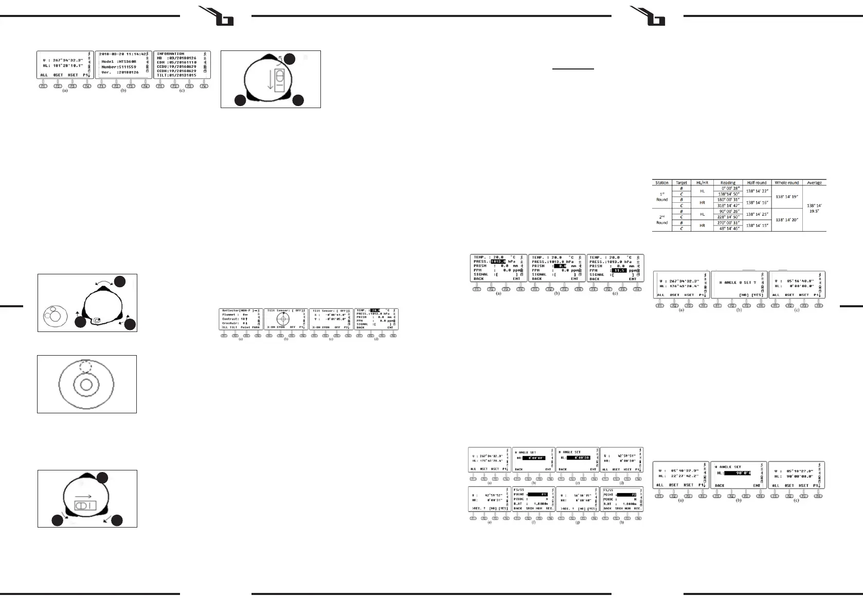
How to measure the horizontal angle for target B / C by
repeated observation?
a. Aim at object B in horizontal left (HL) mode, press F3
HSET, then input the value 0 ° 00 ‚30 „.
Press the F1 ALL and F4 YES buttons to save the
result. Input the point name for target B. Press F4
REC again to save the data to the current le.
b. Turn the device clockwise to aim at object C.
Press the F1 ALL and F4 YES buttons to save the result
and the point name. Press F4 REC again to save the
data.
c. Turn the EDM vertically in the Horizontal Right (HR)
mode. Press the F1 ALL and F4 YES buttons to save
the result and the point name. Press F4 REC again to
save the data.
d. Turn the device anti-clockwise to aim at target B.
Press the F1 ALL and F4 YES buttons to save the result
and the point name. Press F4 REC again to save the
data.
Press F3 HSET the second time and input the value
90 ° 00 ‚30 „. Measure and record the data as in the
above steps. The <BAC value can be calculated as
follows:
F2 OSET:
Setting the current horizontal angle. To set the current
horizontal angle, press the F2 OSET key, then F4 YES to
conrm.
F3 HSET:
Input values. User can separate degrees / minutes / seconds
by inserting a period ‚.‘.
4.2. Page 2
F1 HOLD:
„HOLD“ is used to hold the reading from the horizontal disc
while turning the device.
How to maintain the HL reading at 90 ° 00‘35 „for the
target?
a) Turn the device and set a horizontal angle close to
90 ° 00‘35 „, then adjust the tangential screw until the
desired value is reached.
b) Press the HOLD button to enter the page. Then
loosen the horizontal tangential screw and aim at
the target. At this point, the horizontal angle will not
change.
c) Press YES to conrm.
F2 REP .:
REP (repeat measurement). To repeat the measurement
requires measurement at a right horizontal angle, equal to
the annotation on the horizontal dial, clockwise.
Position the device at point A. The following are the
guidelines for the triple measurement method <BAC:
a) Aim at point B, press REP. The HR is 0 ° 00 ‚00 „
b) Turn the device clockwise, aim at point C, press HOLD
c) Turn the device clockwise, aim at point B a second
time, press F3 REL to release.
EN EN
A
B
C
A B
C
A B
C
Bekijk gratis de handleiding van Steinberg SBS-THE-600, stel vragen en lees de antwoorden op veelvoorkomende problemen, of gebruik onze assistent om sneller informatie in de handleiding te vinden of uitleg te krijgen over specifieke functies.
Productinformatie
| Merk | Steinberg |
| Model | SBS-THE-600 |
| Categorie | Niet gecategoriseerd |
| Taal | Nederlands |
| Grootte | 19988 MB |


