Simrad Recon UI Board handleiding
Handleiding
Je bekijkt pagina 5 van 8
5
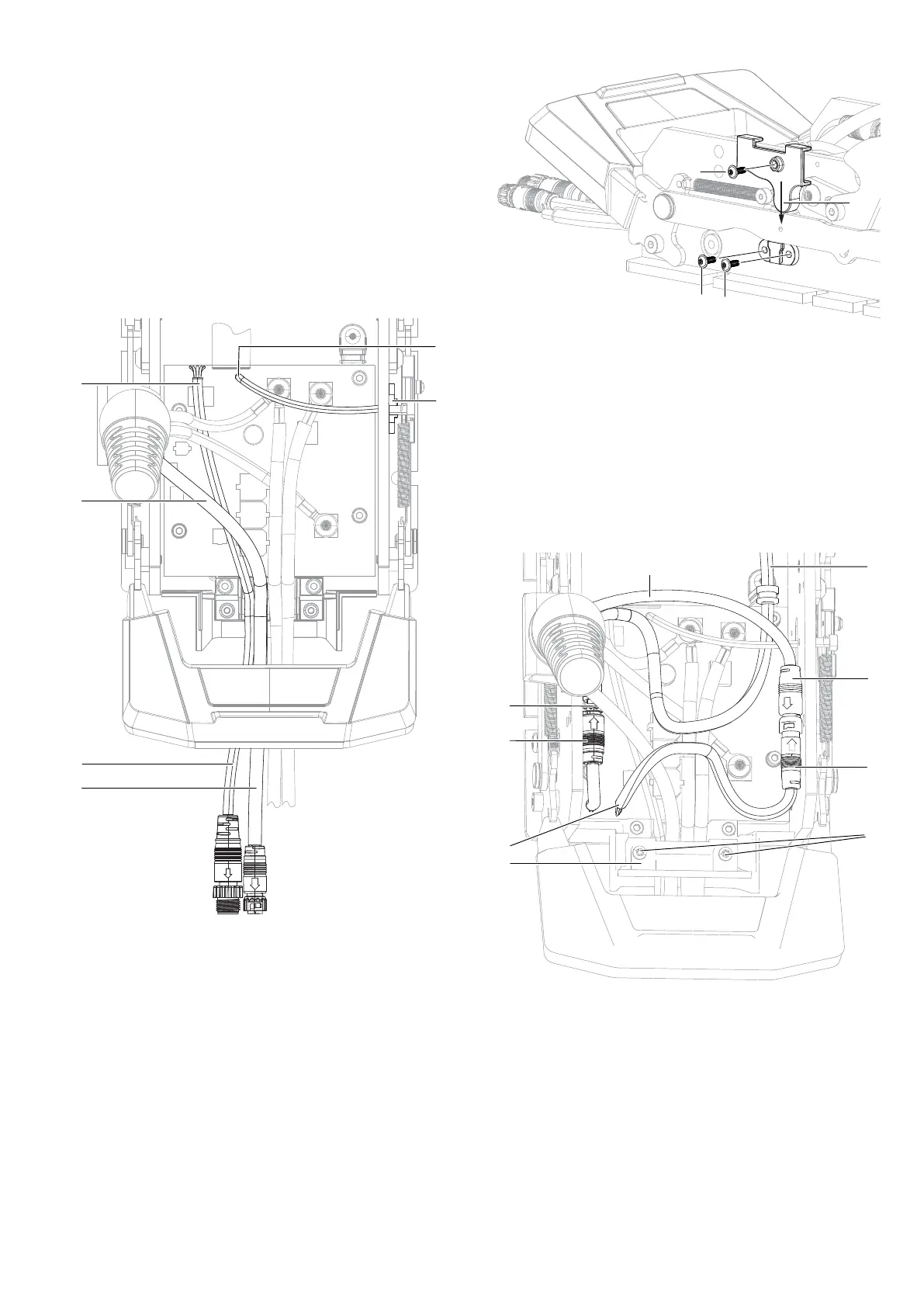
To position the NMEA 2000
®
, sonar, and stow sensor cables:
1 Route the NMEA 2000
®
cable (A) under all other cables,
and pass it out the rear of the mount through the left
channel in the lower routing bracket (marked NM on the
inside of the lower routing bracket).
2 Identify the sonar cable (B) and pass it out out the rear
of the mount through the channel to the right of the
NMEA 2000
®
cable (marked SR on the inside of the
lower routing bracket).
3 The stow sensor cable is attached to the mount
controller board at C. Feed the stow sensor (D) through
the hole in the starboard (right) side of the mount.
¼ Note: In the diagram below, some cables have been
removed for clarity.
C
D
A
B
B
A
To install the stow sensor:
4 Make sure the stow sensor cable is not twisted when
the stow sensor is in position flat against the outside
of the mount. Use a 2 mm Allen key to install two M3-
0.5 x 8, flange screws (E, supplied) securing the stow
sensor to the outside of the mount, and tighten to torque
0.35Nm(3 in‑lb).
5 Fit the stow sensor magnet holder (F) over the linkage
on the outside of the mount, with the magnet facing
inwards. Align the hole in the magnet holder to the hole
in the linkage.
6 Insert a third M3-0.5 x 8, flange screw (G, supplied) for
the magnet holder and tighten it using a 2 mm Allen key.
The screw ensures the magnet is in the correct position
for the stow sensor to work. Tighten to torque 0.35 Nm
(3 in-lb).
G
E
E
F
To connect the communication cable and transmission
cable:
1 The communication cable (A) exits the base of the coil
cable. Fit the communication cable into the molded
connector with the blue mark on the mount controller
board (B).
2 The transmission cable (C) exits the trolling motor
steering transmission. Fit the transmission cable into
the molded connector with the red mark on the mount
controller board (D).
C
C
A
D
B
B
A
E
F
3 Reinstall the upper routing bracket (E, supplied) over the
four cables at the rear of the mount.
¼ Note: Replacing the upper routing bracket is only
necessary if you have stripped the routing brackets’
screw bosses.
4 Use two #6 x 3/4 pan head screws (F, supplied. These
3/4 inch-length screws are the longer T15 Torx
®
screws
supplied in the service kit). Tighten with a T15 Torx
®
bit
or screwdriver. Tighten to torque 1.00 Nm (9 in-lb).
Bekijk gratis de handleiding van Simrad Recon UI Board, stel vragen en lees de antwoorden op veelvoorkomende problemen, of gebruik onze assistent om sneller informatie in de handleiding te vinden of uitleg te krijgen over specifieke functies.
Productinformatie
| Merk | Simrad |
| Model | Recon UI Board |
| Categorie | Niet gecategoriseerd |
| Taal | Nederlands |
| Grootte | 1959 MB |


