Simrad Active Imaging HD (Thru-Hull) handleiding
Handleiding
Je bekijkt pagina 14 van 32
14
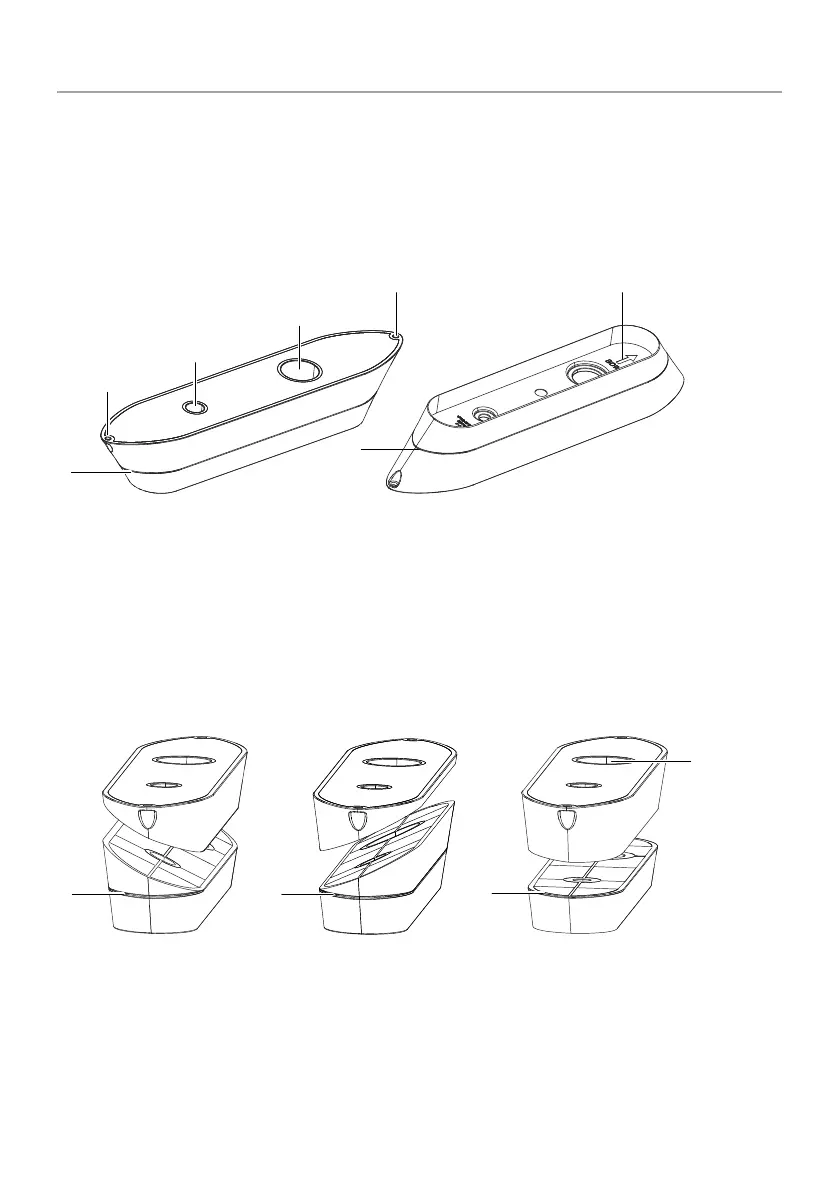
FAIRING BLOCKS
The fairing block ensures the face of the installed transducer is parallel to the waterline.
Before installing a thru-hull transducer and fairing block, the fairing block must be measured and cut to t
against the hull. Both the top and bottom pieces of the cut fairing block are needed for the installation.
The groove (A) around the fairing block is where the fairing block should be cut if you are installing the
transducer on a at (0° deadrise) section of hull. Cuts should not cross below the plane marked by (A).
An arrow on the underside of the fairing block (E) shows which end of the fairing block is towards the bow.
A
B
B
D
C
E
A
A Groove on fairing block
B Holes used to attach fairing block to timber for cutting
C Hole for anti-rotation stud
D Hole for transducer stem
E Arrow showing forward (bow) direction
A dual installation requires two fairing blocks. The cut for the starboard fairing block (C) is angled in the
direction opposite to the cut for the port fairing block (B).
¼ Note: Never cut the fairing block lower than plane marked by the groove on the fairing block (A).
A
A
B DC
E
A
A Groove on fairing block
B Fairing block cut for port side installation
C Fairing block cut for starboard side installation
D Fairing block cut forinstallation on a at hull
E Hole for transducer stem at front (bow) end
Bekijk gratis de handleiding van Simrad Active Imaging HD (Thru-Hull), stel vragen en lees de antwoorden op veelvoorkomende problemen, of gebruik onze assistent om sneller informatie in de handleiding te vinden of uitleg te krijgen over specifieke functies.
Productinformatie
| Merk | Simrad |
| Model | Active Imaging HD (Thru-Hull) |
| Categorie | Niet gecategoriseerd |
| Taal | Nederlands |
| Grootte | 3264 MB |

