Schneider Altivar 71 VW3A7201 handleiding
Handleiding
Je bekijkt pagina 36 van 38
36 1757361 06/2012
Troubleshooting
The 4 LEDs on the cover of the braking unit display the operating conditions. For simplified display during operation and the first time the
unit is turned on, similar LEDs are placed on the control card. The orange and green LEDs are separate on the control card, while there is
a two-color LED (green/orange) on the cover.
Tripping on VCE:
The braking unit trips via the VCE protection circuit, if the specific maximum current of the device is exceeded. The principle of this protection
circuit means that for a short time (less than a millisecond), the IGBT is subjected to stress beyond its specifications for normal operation.
In an exceptional case this is no problem for the braking unit. However, if there are frequent or periodic current surges at braking voltage,
the high power semi-conductors will age rapidly and become prematurely faulty.
The cause of periodic tripping on VCE may be an overload, a fall in line voltage, an oscillating or faulty drive, an oscillating input reference
or poor design of the equipment.
LED messages
CAUTION
RISKS OF INTERFERENCE
If the braking unit trips during a slow-down, it must not be reset to zero before the end
of the slow-down, or before the DC bus voltage has fallen to a normal value.
To avoid any problems, you can block the release of the inverter pulse by connecting
the general fault relay contact on the braking unit to the corresponding connection on
the frequency inverter.
Failure to follow these precautions can result in equipment damage.
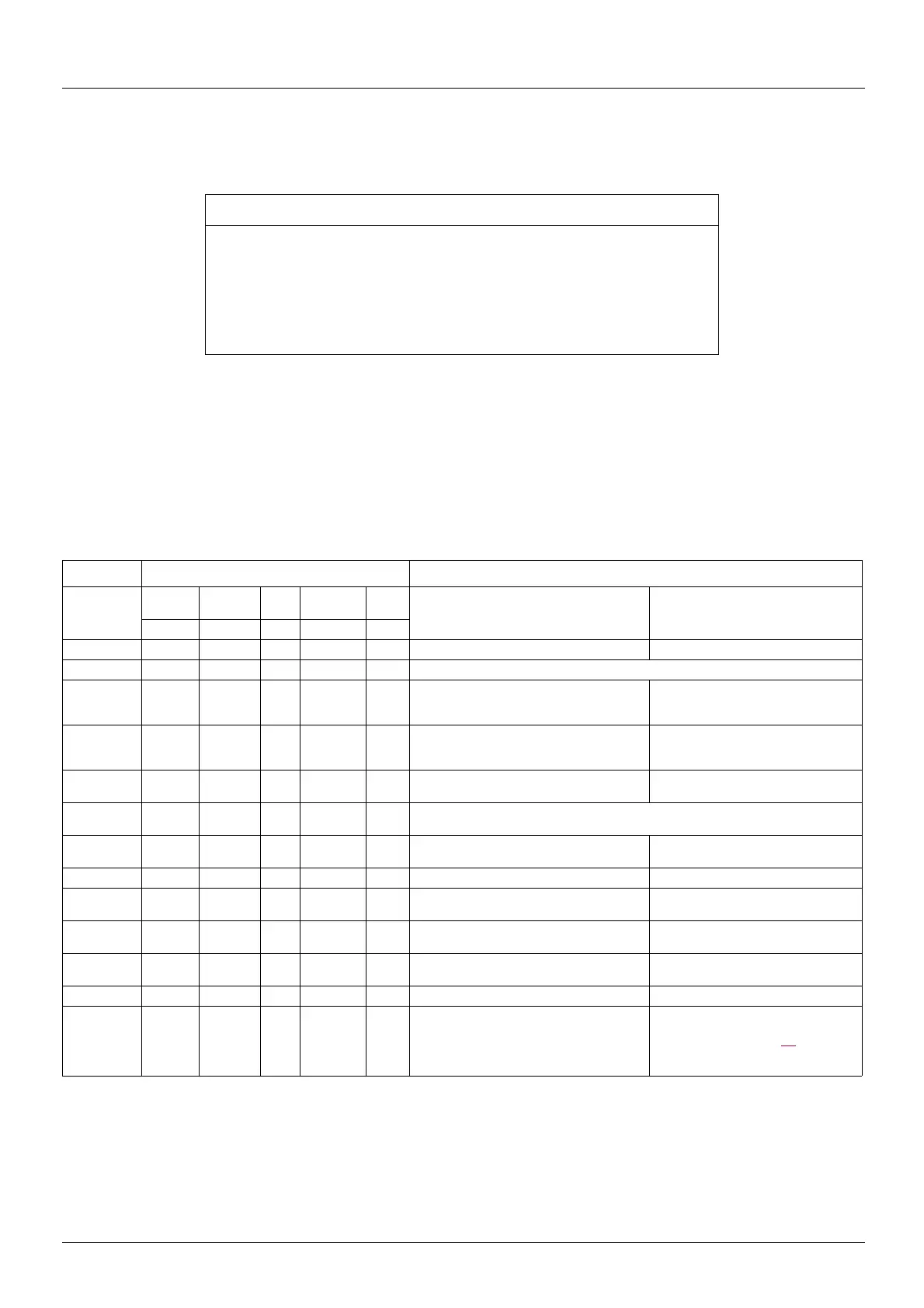
LED display Assessment
LED display
fault code
Operati
on
Phase
loss
VCE Overheatin
g
Fault First start (after approx. 1 s) During operation
green red red orange yellow
1 X Ready to operate System in operation
2 X Ready to operate, but no power generated ⇒ check the DC fuse
3 X X X Heatsink overheating ⇒ error message
cannot be reset to zero while overheating
continues
4 X X Fault code 3 ⇒ the heatsink temperature
has fallen to normal and the fault can be
reset to zero
5 X X The system has stopped, (external OFF) ⇒
reset to zero required
The system has stopped, (external OFF)
⇒ reset to zero required
6 X X An overvoltage has been detected (J8 closed) => a reset to zero is required when the grid
voltage falls to its nominal value
7 X X X Incorrect phase rotation direction or a phase
missing.
Phase loss detected => reset required
8 X X X Overcurrent detected => reset required
9 X X X X Faults 7 and 8 Overcurrent and phase loss detected
simultaneously
10 X X X X X Several faults have been detected
simultaneously
Several faults have been detected
simultaneously
11 System stopped, at least 2 phases missing System stopped, at least 2 phases
missing
12 X X Trip-I2t => reset required
13 X X Voltage drop during switching but no trip,
while jumpers 3 and 7 are open (See the
“Configuration”, page 34) =>
operation possible, improvement of the
line voltage recommended.
Bekijk gratis de handleiding van Schneider Altivar 71 VW3A7201, stel vragen en lees de antwoorden op veelvoorkomende problemen, of gebruik onze assistent om sneller informatie in de handleiding te vinden of uitleg te krijgen over specifieke functies.
Productinformatie
| Merk | Schneider |
| Model | Altivar 71 VW3A7201 |
| Categorie | Niet gecategoriseerd |
| Taal | Nederlands |
| Grootte | 2581 MB |


