RIDGID 918-5 handleiding
Handleiding
Je bekijkt pagina 11 van 111
9
918 Roll Groover
999-998-946.10_REV D
appropriate base can be used with the 100A/150A/200A
stands.
1. Confirm that the 918 is properly assembled on the
correct base for the machine it will be used with.
2. Position machine carriage towards front chuck and
swing carriage mounted tools up away from the
operator. Position reamer inside the die head to
secure and reduce risk of contact.
3. Fully open front chuck of threading machine. Insert
drive bar into machine chuck, but do not secure at
this time.
4. Place the open slot (pump side) of the base over the
front carriage rail (Figure 8B) and lower the stabilizer
to the rear carriage rail.
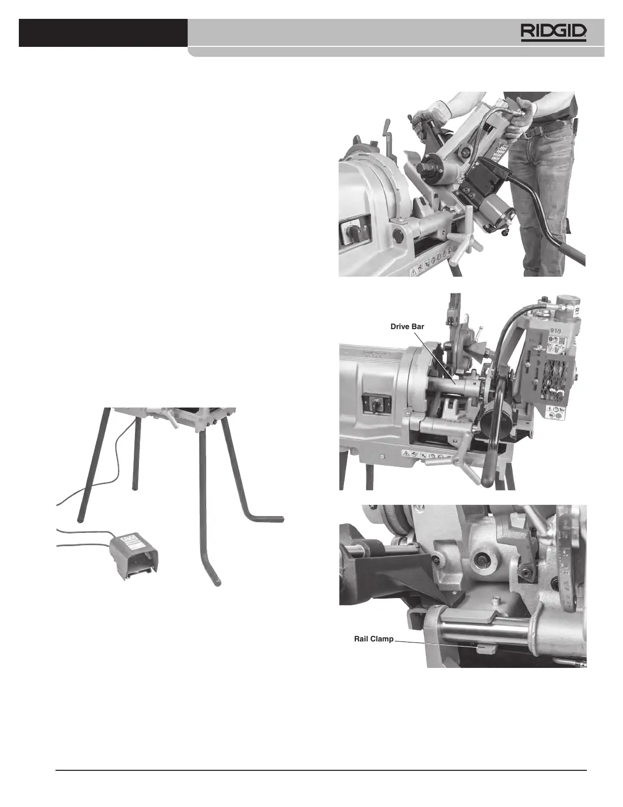
5. Place the drive bar over the drive shaft flats. Align the
drive shaft flats with set screws in the drive bar and
securely tighten the set screws.
6. With the 918 positioned at the end of the threading
machine securely tighten the machine front chuck on
the drive bar. See Figure 8C.
7. Place the rail clamp under the rear carriage rail and
secure. See Figure 8D.
Figure 8A – Catalog #56532 Legs with feet installation
Figure 8B – Installing 918 on 1233 Threading Machine
Figure 8C – Drive Bar Installation
Figure 8D – Installing Rail Clamp
Installing On 535 and 1224 Threading
Machines
Generally, the 918 can be installed on the 535 and 1224
machines with the drive bar installed, but it can also be
9
Drive Bar
Rail Clamp
Bekijk gratis de handleiding van RIDGID 918-5, stel vragen en lees de antwoorden op veelvoorkomende problemen, of gebruik onze assistent om sneller informatie in de handleiding te vinden of uitleg te krijgen over specifieke functies.
Productinformatie
| Merk | RIDGID |
| Model | 918-5 |
| Categorie | Niet gecategoriseerd |
| Taal | Nederlands |
| Grootte | 42226 MB |


