Power Soak SKS-70 handleiding
Handleiding
Je bekijkt pagina 8 van 10
8 OM-SKEWER SOAK
Faucet Installation
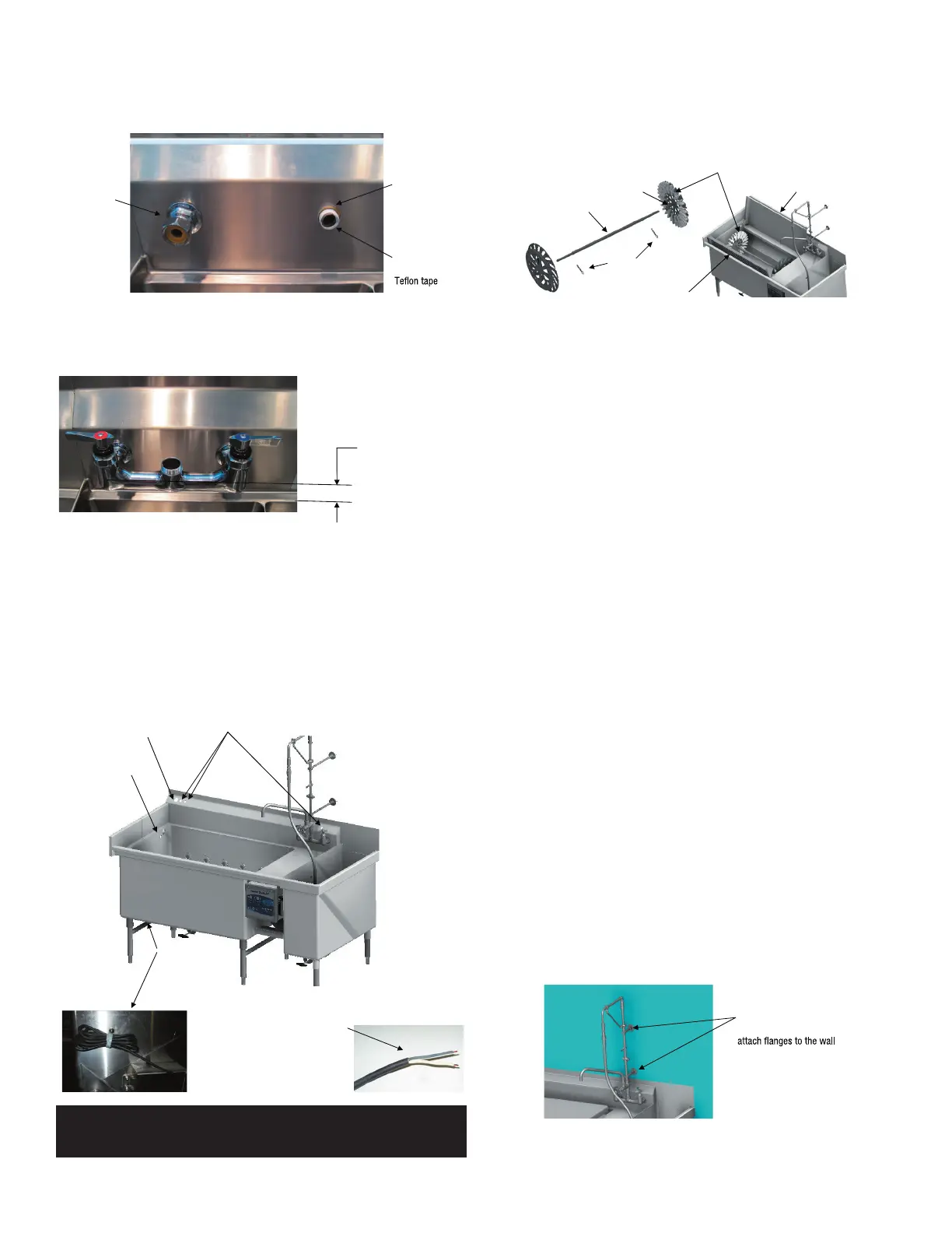
Open the faucet package and locate the water connection elbows, faucet body and
escutcheon assemblies. Apply Teflon tape to the threads of the elbows and insert them
though the backsplash of the sink.
Escutcheon
screwed onto
the elbow
Elbow inserted
from the back
side of the
backsplash
Wrap the elbow
threads with
Loosely fit the escutcheons to the elbows and the faucet body. When the alignment
of the body with the sink is confirmed, tighten the escutcheons onto the elbows and
faucet body. From the back side of the backsplash, tighten the brass nuts on the
elbows when the faucet body is parallel with the rim of the sink.
Faucet must be parallel
with the drain board or rim
of the sink
Complete the faucet assembly according to the manufacturer’s instructions which
are included with the faucet. Attach water lines to the faucet so that the lines extend
below the sink. This will make the plumbing easier to complete when the machine is
placed against the wall.
Chemical Dispenser
A chemical dispenser is purchased separately from another manufacturer. The
installation instructions for the chemical dispenser will be provided by the chemical
dispenser manufacturer. The Skewer Soak is equipped with holes in the backsplash
for an electrical connection and tubing for a chemical dispenser. The Skewer Soak
also has an electrical cable for operating the chemical dispenser.
The electric cable for operating the
chemical dispenser is a two wire cable
that will be bundled under the wash
tank. The wires must be connected to
a chemical dispenser or disconnected
from the electrical system of the
machine.
Chemical Sensor
mounting hole
Hole for electric cable
Holes for tubing
Electric cable
for signaling
the chemical
dispenser
IMPORTANT:
THE ELECTRIC CABLE FOR THE CHEMICAL DISPENSER MUST BE
CONNECTED TO A CHEMICAL DISPENSER OR DISCONNECTED FROM THE
SKEWER SOAK ELECTRICAL SYSTEM.
Skewer Rack, Cover and Work Tray
The Skewer Rack will need to be assembled and placed in the wash tank. Slide the
end wheel assemblies onto the shaft with the center sleeve of the wheel assembly
oriented toward the middle of the shaft. Align the hole in each sleeve with the hole in
the shaft and insert the pins to secure the wheels on the shaft.
Shaft
Pins
Wheel Assembly with retainer clips
installed on the left side of the wash tank
Sleeve Rear cover
Work Tray
Orient the wheel with the retainer clips toward the left side of the wash tank and place
the Skewer Rack assembly in the wash tank suspended in the bearings. The Skewer
Rack must spin freely in the bearing blocks. The Skewer Rack is rotated by the flow
of the water in the tank.
Place the rear cover so that the pivot pins slide into the bearing blocks at the back
of the tank. Lower and raise the cover to make certain that it pivots properly in the
bearings. Place the work tray so that the pivot pins slide in to the bearing blocks at the
front of the wash tank. Lower and raise the work tray to make certain that it pivots in
the bearing blocks properly.
COMPLETING THE INSTALLATION
FINAL INSTALLATION STEPS
Machine Placement
Position the Skewer Soak so that the back splash rests against the wall and is placed
according to the floor plan or customer’s selected location. Examine the drain and
water supply lines to determine that the plumbing can be completed when the Skewer
Soak is in the final location. Verify that the plumbing from the faucet and overflow
drain (suggested in earlier sections) can be reached with the sink against the wall.
Level and Attach to the Wall
Using a level, adjust the feet on the Skewer Soak until the front rim and the rear rim
of the sink are level. The sink must also be level front to back. Locate the wall studs
and mark their location on the top edge of the back splash. Measure down ¾” from
the top of the backsplash and then drill ¼” diameter holes through the back splash in
line with the center of the studs. Use the #10 stainless steel screws (included with the
Skewer Soak) to attach the skewer soak directly to the wall.
Seal around the Backsplash and Screws
Examine the installation to see that the wall and backsplash are clean and free of
dust and oils. Seal the top and sides of the backsplash to the wall using the clear NSF
approved sealant provided with the Skewer Soak. Seal around the screw heads to be
sure they do not allow water to leak behind the backsplash. Wipe off all excess sealant
leaving a smooth, clean and sanitary bead of sealant on all the edges.
Riser Anchor Installation
Follow the faucet manufacturer’s directions on the assembly of the faucet and riser.
Anchor the riser supports to the wall using the flange plate provided with the riser
assembly. It may be necessary to cut the support rods to a shorter length in order to
fit between the wall and the riser.
Cut the riser support rods
to the proper length and
Plumbing Connections
Connect the water supply lines to the faucet. Connect all the drains to the waste drain
connection.
Bekijk gratis de handleiding van Power Soak SKS-70, stel vragen en lees de antwoorden op veelvoorkomende problemen, of gebruik onze assistent om sneller informatie in de handleiding te vinden of uitleg te krijgen over specifieke functies.
Productinformatie
| Merk | Power Soak |
| Model | SKS-70 |
| Categorie | Niet gecategoriseerd |
| Taal | Nederlands |
| Grootte | 3637 MB |


