Power Soak SKS-70 handleiding
Handleiding
Je bekijkt pagina 6 van 10
6 OM-SKEWER SOAK
Wall Preparation
Clean the wall(s) where the new Skewer Soak will be installed. Fill all existing holes
with an appropriate filler material (caulk, silicone, hole plug, etc…). Be sure that any
outlet that will be covered by the sink has been disconnected and a water tight cover
has been installed over the opening.
PRE-PLUMBING
Supply and Waste Lines
The supply and waste lines must meet the following requirements:
• Hot and cold water supply must be ½” diameter or larger.
• Center lines of the hot and cold water supply must be 10” or less above the
floor to access the shutoff valves when the machine is installed.
• Waist drain must be 1-1/2” minimum diameter.
• Center line of the waste drain must be 11” or less above the floor to allow the
sink to drain properly.
Install new shut-off valves on the hot and cold water supply lines.
IMPORTANT:
IT IS RECOMMENDED THAT ALL MACHINES BE INSTALLED USING NEW ½”
OR LARGER BALL-VALVE SHUT OFF VALVES.
Grease Trap
It may be necessary to relocate and/or replace the existing grease trap. Be sure that
the grease trap meets or exceeds the local plumbing codes.
IMPORTANT:
WASTE PLUMBING MUST CONFORM TO LOCAL BUILDING CODES.
POST-UNCRATING INSTRUCTIONS
UNCRATING
Remove From Crate
Remove the Skewer Soak from the shipping crate. Sharp staples and nails are used to
crate the machine and care must be taken in handling boards and cardboard to keep
from creating a puncture or injury to people or the equipment. Discard the crating
materials in an appropriate disposal area or container.
Inspect the sink and packages to be certain that there was no damage created by
the shipping company. If there are signs of shipping damage, contact the shipping
company before proceeding.
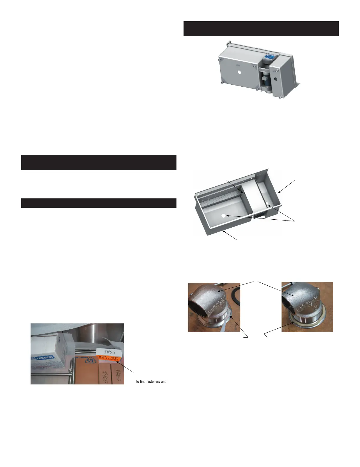
Remove the packages from the Skewer Soak tank and locate the box labeled “OPEN
FIRST”. This box will contain the fasteners and sealant that will be required for
assembly of the Skewer Soak.
Locate the box labeled
“OPEN FIRST”
sealant used for the
installation.
COMPONENT INSTALLATION
Lay the sink on its back to allow access to the bottom of the tanks. Be careful to not
let the sink assembly drop on the floor with an impact that would damage the sink
assembly or the floor.
IMPORTANT:
DO NOT BEND THE EDGE OF THE BACKSPLASH WHEN LAYING THE SINK
ON ITS BACK SIDE.
The sink must be accessible from its top side and its bottom side in order to install
the accessories. Be aware that the backsplash is unsupported at this time and can
be bent out of shape by trying to support the entire weight of the sink on the edge of
the backsplash.
Install Sink Drains
There are two sink drains in the Skewer wash tank and one in the Sanitizer tank that
must be installed. The drain with a valve built into the body is installed in the bottom
of the tank and the drain without a valve built into the body is installed in the side wall
of the Skewer wash tank at the top.
OVERFLOW DRAIN AT
TOP DOES NOT HAVE A
BUILT IN VALVE
DRAIN WITH BUILT-IN
VALVE IS INSTALLED
IN THE BOTTOM OF
THE TANK
NOTE:
THE SANITIZER
TANK IS AN OPTION
AND MAY NOT BE
INCLUDED WITH ALL
INSTALLATIONS
SKEWER WASH TANK
Bottom Drain
Each drain flange must be sealed to its mating surface in the sink. Apply a generous
bead of clear silicone sealant (supplied with the machine) around the lip of the drain
body or form a ring of “plumber’s putty” and place it on the lip of the drain body.
DRAIN BODY
CLEAR SILICONE SEALANT
FORMED RING OF PLUMBER’S PUTTY
The drains with built-in valves will be oriented with the handle connection toward
the front of the sink. From inside the sink, insert the drain through the drain hole and
seat the flange against the sheet metal surface of the tank. When using “plumber’s
putty”, be sure that the ring of putty compresses to where the rim of the drain actually
touches the sheet metal surface of the sink. If the drain does not touch the sink it will
work loose and leak as the putty compresses over time.
From the outside of the tank place the rubber vibration ring over the threaded body
of the drain followed by the Teflon ring and then the drain nut. Tighten the nut “hand
tight” until the handle is installed.
Bekijk gratis de handleiding van Power Soak SKS-70, stel vragen en lees de antwoorden op veelvoorkomende problemen, of gebruik onze assistent om sneller informatie in de handleiding te vinden of uitleg te krijgen over specifieke functies.
Productinformatie
| Merk | Power Soak |
| Model | SKS-70 |
| Categorie | Niet gecategoriseerd |
| Taal | Nederlands |
| Grootte | 3637 MB |


