Phoenix Contact FL SWITCH EP7400 handleiding
Handleiding
Je bekijkt pagina 24 van 46
FL SWITCH EP7…
24/46 PHOENIX CONTACT
4083_en_C
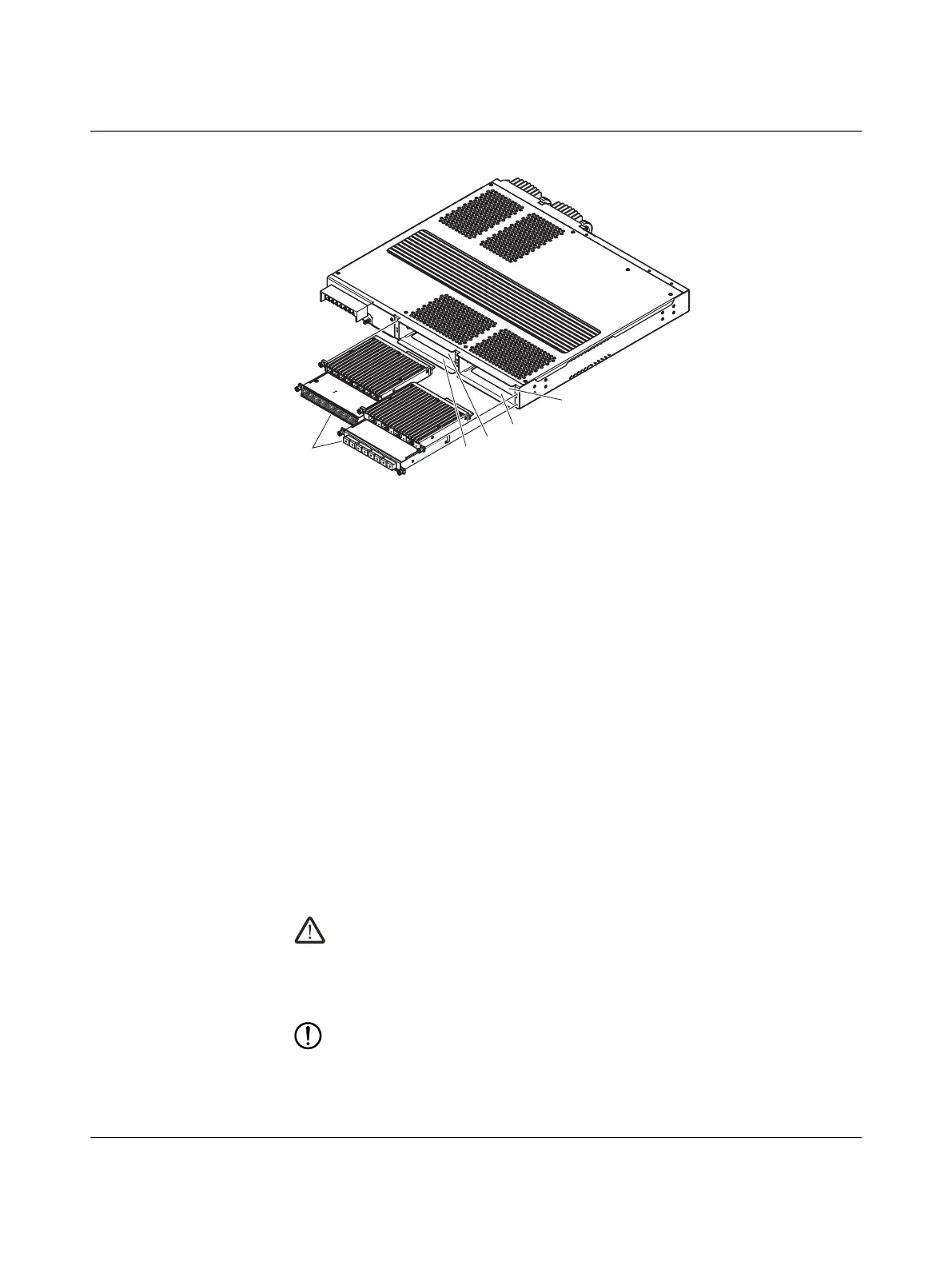
Figure 4-4 Port/line module structure
1. Remove the cover plate (FLSWITCH EP7400-ABLK), if installed.
2. Insert the desired module into an appropriate slot (see table above). Modules insert-
ed into LM1 and LM3 slots must be turned over with the cooling fins down and flat
side up.
3. Secure the module with the module retaining screws. Torque to a maximum of
0.6 Nm.
Removal
To remove a port/line module, remove the screws securing the module in the slot. If a re-
placement module will not be installed, a blank cover (Order No. 1144428) must be in-
stalled on the slot.
4.5.4 SD card
SD cards provide extra Syslog memory and allow manual transfer of Syslog files to a com-
puter.
4.6 Connections
Voltage supply conductors are connected directly to the rear of the switch, not the power
supply modules.
WARNING:
Ensure the voltage supply is turned off before connecting the voltage supply con-
ductors to the terminals on the switch.
Disconnect all power sources. Device may have multiple power sources.
Ensure the supplied terminal block cover is installed before reapplying power.
NOTE:
Do not connect AC power cables to the FL SWITCH EP7400-PS-MV or FL SWITCH
EP7400-PS-LV modules. Discard and replace modules if this occurs.
LM2
L
M
1
LM
4
LM
3
3
2
1
4
5
Bekijk gratis de handleiding van Phoenix Contact FL SWITCH EP7400, stel vragen en lees de antwoorden op veelvoorkomende problemen, of gebruik onze assistent om sneller informatie in de handleiding te vinden of uitleg te krijgen over specifieke functies.
Productinformatie
| Merk | Phoenix Contact |
| Model | FL SWITCH EP7400 |
| Categorie | Niet gecategoriseerd |
| Taal | Nederlands |
| Grootte | 4097 MB |


