Phoenix Contact ECM-UC-100A-UI handleiding
Handleiding
Je bekijkt pagina 35 van 80
Configuration
111433_en_00 Phoenix Contact 35 / 78
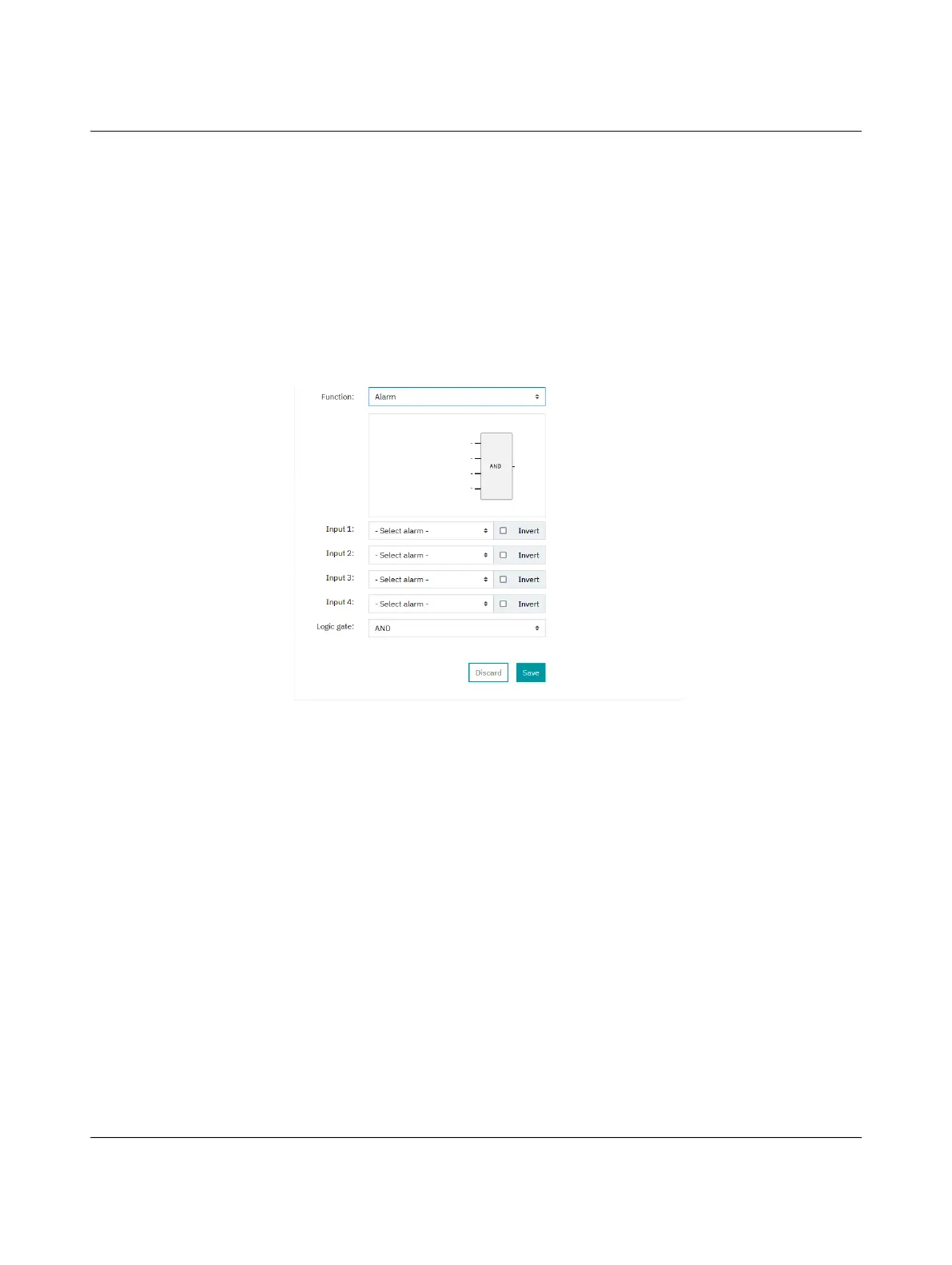
Function
Specify which function is to be performed.
You can select one of the following two functions:
Figure 4-15 Alarm function
Input 1-4
Specify which alarm is used at which input.
The relay and transistor outputs can be assigned alarms independently of one another.
Select the “Invert” option to negate the input signal or alarm signal.
Logic gate
You can link the individual alarms together with a logic gate.
The following options are available:
– AND
– OR
– XOR
– NAND
– NOR
– NXOR
Alarm: The relay or transistor switches when the specified alarm condition is met.
Manually: Activate or deactivate the relay or transistor manually. Please note that an
operating voltage must be applied for this. Only connect one “+24 V” con-
nection terminal block (2.1 or 2.2) and one “GND 1” connection terminal
block (2.3 or 2.4).
See Section 3.4, “Connection assignment”.
Bekijk gratis de handleiding van Phoenix Contact ECM-UC-100A-UI, stel vragen en lees de antwoorden op veelvoorkomende problemen, of gebruik onze assistent om sneller informatie in de handleiding te vinden of uitleg te krijgen over specifieke functies.
Productinformatie
| Merk | Phoenix Contact |
| Model | ECM-UC-100A-UI |
| Categorie | Niet gecategoriseerd |
| Taal | Nederlands |
| Grootte | 6107 MB |


