Nord Modular G2 handleiding
Handleiding
Je bekijkt pagina 243 van 291
NORD MODULAR G2 V1.4x 13. Module reference: Sequencer group
Page 243
S
EQ
V
AL
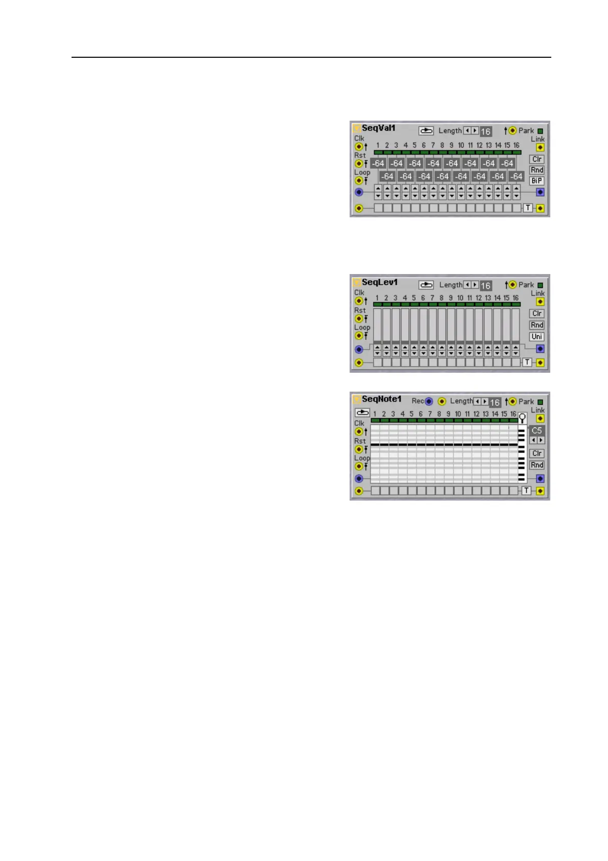
This is a sequencer which sends one control signal value
for each step. The value for each step is shown in the
corresponding display box. In Unipolar mode (the Uni
button depressed), the values are displayed in steps of
0.5 units. Every half-step (.5) is indicated by a dot to the
right of the full step value. For example, the value 5.5 is
displayed as ‘5 .’. There is also a row of Step buttons for
sending out a Trig/Gate signal for every step in the
sequence. See also "Common Sequencer parameters”.
S
EQ
L
EV
This is a Level Sequencer which sends a control signal
level for each step. It is ideal for sequencing modulation
patterns. There is also a row of Step buttons for sending
out a Trig/Gate signal for every step in the sequence.
These buttons can also be used to flag extra accents in a
pattern. See also "Common Sequencer parameters”.
S
EQ
N
OTE
This is a Note Sequencer which sends a (bipolar) control
signal value for each step. If you route this control signal
to an unattenuated Pitch modulation input on an
Oscillator module, the note value displayed in the hint
box will correspond exactly to the output Oscillator
Pitch. There is also a row of Step buttons for sending out
a Trig/Gate signal for every step in the sequence.
R
EC
V
ALUE
AND
R
EC
E
NABLE
INPUTS
This module has a nice feature that lets you record values ‘on the fly’. To use this feature a control signal
has to be connected to the blue Rec input. The yellow Rec Enable input next to the blue Rec input
switches the module between sequencer mode and recording mode. When a steady logic
HIGH
level is
applied to the Rec Enable input two things happen, the first thing you will hear is that the value-row
output will stop outputting the value-row but switch to monitor the Rec input. The second thing is that
while you hear the monitor signal the sequencer will sample the steps on the positive edges of the Clk
signal. Meaning that the moment it advances to a new step it samples the Rec input and stores it in the
step. New values are stored as long as the yellow Rec Enable input receives a logic
HIGH
and the Clk
input receives clock pulses. The way values are stored is similar to how values are sampled by a S&H
module, but with this module you won’t hear the stored values until the Rec Enable input is brought to
a logic
LOW
. Note that when the signal on the blue Rec input is a smooth signal like e.g.an Lfo triangle
waveform the output signal will also be smooth when in Rec mode, as the value quantization will only
happen while the Rec input value is actually stored and not be available before when the Rec signal is sent
to the output to be monitored. When comparing with a S&H it is like the input of the S&H is monitored
and not its output.
P
IANO
ROLL
WINDOW
AND
MARKERS
Each step in the sequence is displayed as a row of keyboard keys, with the grey lines representing the
black keys and the white fields representing the white keys. You set the control signal level (note number)
Bekijk gratis de handleiding van Nord Modular G2, stel vragen en lees de antwoorden op veelvoorkomende problemen, of gebruik onze assistent om sneller informatie in de handleiding te vinden of uitleg te krijgen over specifieke functies.
Productinformatie
| Merk | Nord |
| Model | Modular G2 |
| Categorie | Niet gecategoriseerd |
| Taal | Nederlands |
| Grootte | 60689 MB |


