Nord Modular G2 handleiding
Handleiding
Je bekijkt pagina 236 van 291
13. Module reference: Logic group NORD MODULAR G2 V1.4x
Page 236
level and the Q-Bar output to a logic low level. The S input is in fact the opposite of the Rst input, but
when the Rst input is also brought high the Rst will have priority over the S input.
The RS-type flipflop can also toggle the states on the Q and Q-Bar outputs automatically when a clock
signal is connected to the Clk input. For this to work both the Rst and the S input must be permanently
low. When in toggling mode and the S and/or the Rst inputs receive a constant logic high level, the
toggling will stop as both the S and the Rst inputs have priority over the Clk input on a RS-type flipflop.
See also "Common Logic module parameters”.
C
LK
D
IV
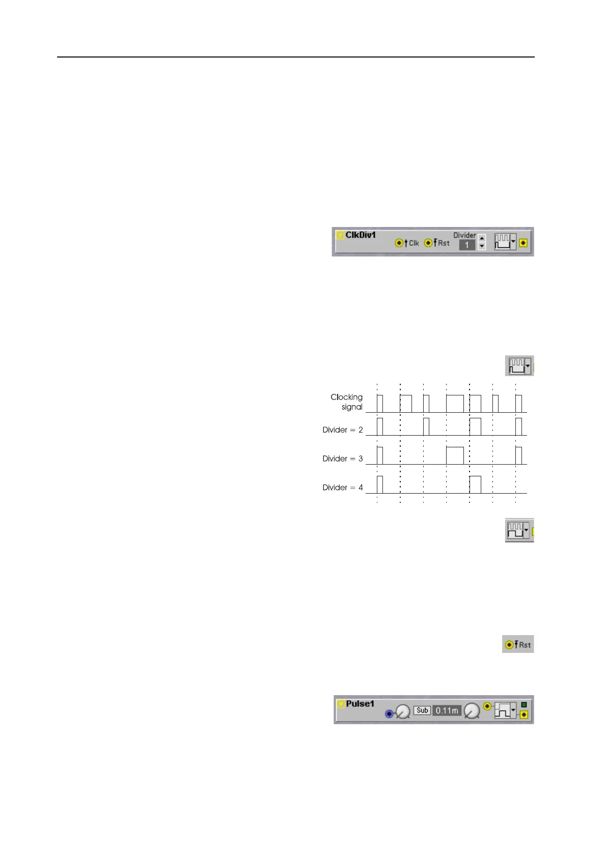
The Clock Divider module can be used for dividing
incoming clock pulses by a factor ‘n’, which can be set
with the Divider control. This module has two possible
modes that can be set by the dropdown control.
D
IVIDER
Set the desired division with the buttons. Range: 1 to 128. The division denominator is shown in the
Display box.
G
ATED
M
ODE
In this mode the module will pass on every n-th clockpulse on the Clk input. The shape of the
input clockpulse is left unaltered.
In the schematic to the right you see how the
original train of clock pulses will be passed on to the
output. You can see how the pulse length of clock
pulses is maintained in the divided clock signal at the
output of the module. If the Divider control is set to
1 the incoming train of clockpulses is passed
unaltered to the output.
T
OGGLED
M
ODE
In this mode the output of the ClkDiv module will toggle its logic output state on every n-th edge
of a clockpulse on the Clk input. If the clock signal is at a steady rate the output signal will be a
squarewave signal at e.g. half the clocking rate when the Divider is set to two.
Note that both the positive or rising edge and the negative or falling edge in the input signal can toggle
the output state. This means that when the Divider control is set to e.g. 3 the actual frequency of the
input signal is divided by one and a half.
D
ELAYED
R
ST
INPUT
The Rst input has a barred arrow symbol. Note that this means that the resetting action will be
delayed until the next positive edge of the clocking signal on the Clk input.
P
ULSE
This module will generate a logic
HIGH
pulse of a set
duration on the moment it receives a logic signal on its
input. The duration of the logic
HIGH
pulse can be set in
three ranges, range Sub is from 0,1 msec to 1 second, range Lo from 1 msec to 10 seconds and range Hi
Bekijk gratis de handleiding van Nord Modular G2, stel vragen en lees de antwoorden op veelvoorkomende problemen, of gebruik onze assistent om sneller informatie in de handleiding te vinden of uitleg te krijgen over specifieke functies.
Productinformatie
| Merk | Nord |
| Model | Modular G2 |
| Categorie | Niet gecategoriseerd |
| Taal | Nederlands |
| Grootte | 60689 MB |


