Nord Modular G2 handleiding
Handleiding
Je bekijkt pagina 235 van 291
NORD MODULAR G2 V1.4x 13. Module reference: Logic group
Page 235
F
UNCTION
DROP
-
DOWN
SELECTORS
Click the Function drop-down selector to alter the processing function of the module. Note
that changing a function with drop-down selectors will force the Sound engine to optimize the
DSP
resources and thus cause a brief moment of silence.
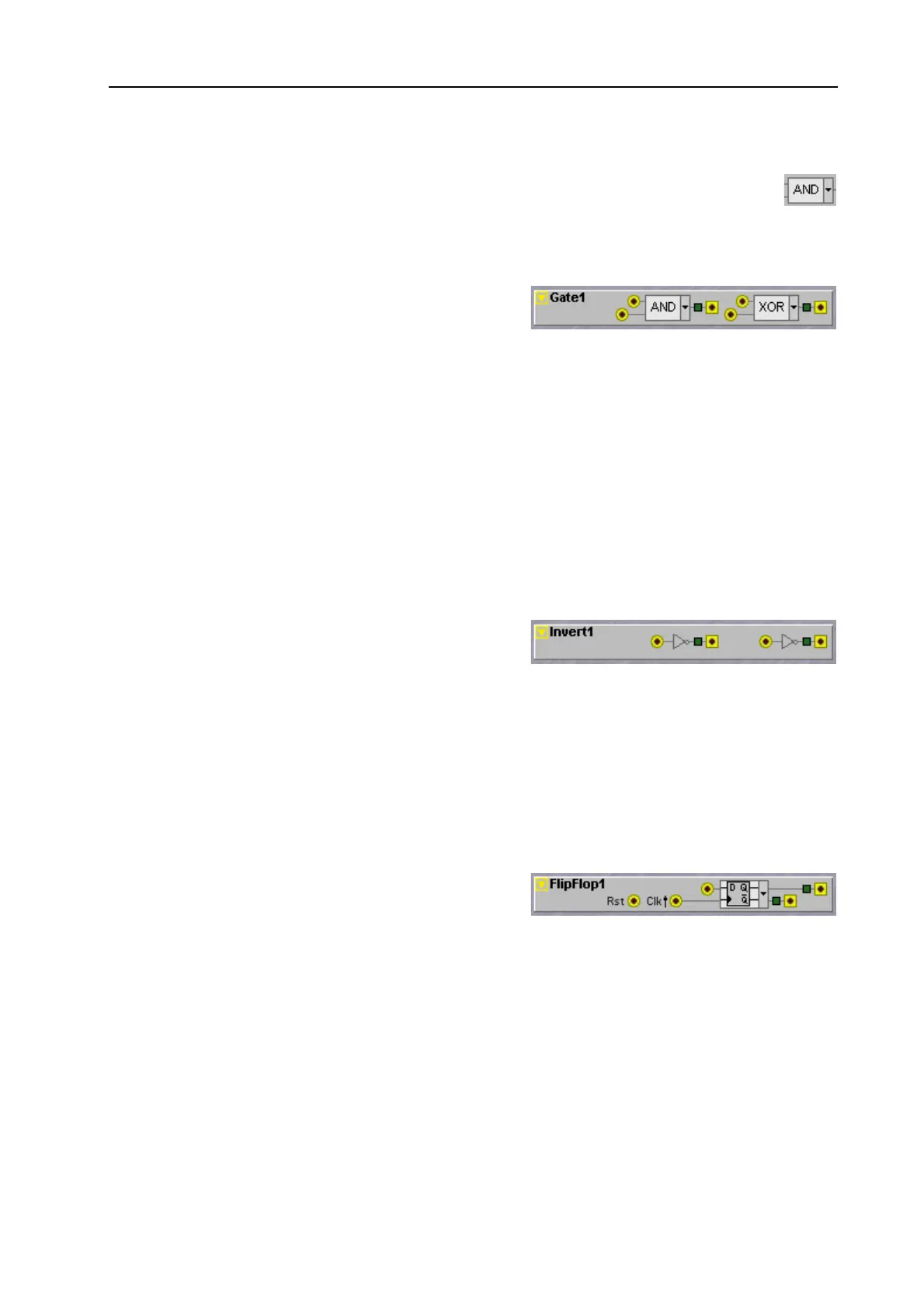
G
ATE
This module features two independent logic gates. A
gate is a device that combines two logic levels, in a way
that is a bit similar to how a mixer mixes two audio
signals. Like a two channel mixer, each gate has two inputs and one output, but there are actually several
different combining functions possible on two logic signals. For each different combining function there
is a different gate type available. You select this gate type from the drop-down selectors. The gate types
on this module are: AND, NAND, OR, NOR, XOR and XNOR. The respective gate functions are
described with truth tables that are visible when you click the drop-down selector. In the truth table you
see which combination of logic values gives which output signal. See also "Common Logic module
parameters”.
Note that the word ‘gate’ comes from the electronics world where it is the name for a group of digital
devices. Gate devices are something completely different than the Keyboard Gate signal that comes from
the keyboard to signal that a key is pressed, although the same word is used for both. Still, gate devices
can be put to good use to process the Keyboard Gate signal.
I
NVERT
The Invert module holds two independent logic
inverters. When an incoming signal is at a logic
LOW
state the output will transmit a logic
HIGH
. When an
incoming signal is at a logic
HIGH
state the output will transmit a logic
LOW
. So, the output is always the
inverse of the input. See also "Common Logic module parameters”.
Tip! When an output is connected to its own input the Inverter will start to produce a squarewave signal
at 12kHz if the module is yellow and a squarewave signal at 48kHz when the module is orange. These
very high frequency signals can be used to e.g. clock a clocked random module with Rst and Seed inputs
to produce what is named synced noise.
F
LIP
F
LOP
The FlipFlop module holds two different functions
named a D-type flipflop and a Set-Reset flipflop.
T
HE
D-
TYPE
FLIPFLOP
The D-Type flipflip will clock the logic state on the D input to the Q output on the positive edge of a
clock signal on the Clk input. The Q-Bar output will always be the inverted state of the Q output.
Whenever there is a logic
HIGH
signal present on the Rst input the Q output will become ‘always low’
and the Q-Bar ‘always high’ and the flipflop will ignore any clocking commands until the Rst input is
brought low again.
T
HE
S
ET
-R
ESET
FLIPFLOP
When the module is set to the Set-Reset type flipflop (or RS-type flipflip) the D input changes into a S(et)
input. When the S input receives the positive edge of a clock pulse it will set the Q output to a logic high
Bekijk gratis de handleiding van Nord Modular G2, stel vragen en lees de antwoorden op veelvoorkomende problemen, of gebruik onze assistent om sneller informatie in de handleiding te vinden of uitleg te krijgen over specifieke functies.
Productinformatie
| Merk | Nord |
| Model | Modular G2 |
| Categorie | Niet gecategoriseerd |
| Taal | Nederlands |
| Grootte | 60689 MB |


