Nord Modular G2 handleiding
Handleiding
Je bekijkt pagina 234 van 291
13. Module reference: Logic group NORD MODULAR G2 V1.4x
Page 234
LOGIC GROUP
These modules can generate and combine logic signals in a number of different ways. A logic output
signal will have one of only two states: a logic
HIGH
, which always corresponds to a value of +64 units
and a logic
LOW
, which always corresponds to a value of 0 units. But the edges of logic signals can be very
important as well, edges are when a logic signal changes from
LOW
to
HIGH
, which is named the positive
edge or from
HIGH
to
LOW
which is named the negative edge. Edges can specify a precise moment in time
when you want something to happen, like playing a note or advance a sequencer to its next step.
Triggering will always use the positive edge of a logic signal and doesn’t care how long the logic signal
stays in its
HIGH
state.
Getting everything in perfect timing means many times to delay the edges of logic signals to moments in
time specified by e.g. the positive edges of the pulses in a master clock signal. In this group you will find
modules that can help you to synchronize events to a master clock.
Note that synchronization is very important in music. Still, many times it is not at all that easy and obvious
how to do it. In fact synchronization is an art by itself that takes some time to master. Our advise is to
take the time it takes and learn it one step at a time. As you will find out this is also how logic works; step
after step.
Read more about logic signals at “Logic or gate signals, yellow and orange connectors” on page 135.
C
OMMON
L
OGIC
MODULE
PARAMETERS
L
OGIC
SIGNAL
INPUT
(
S
)
The D
YNAMIC
C
ONTROL
/A
UDIO
signal input(s). If you input an audio signal, the color of the
input(s) and logic signal output(s) change color to orange to indicate that the module has adapted
itself for audio rate bandwidth. Any positive value in the input signal will be interpreted as a logic
HIGH
signal on a logic input. Any negative value or a value of zero will be interpreted as a logic
LOW
signal on
a logic input. So, if the input signal is not already a logic signal, it will first be transformed at the input to
a logic signal according to the previously describe ‘rules’ before being used internally in the module.
L
OGIC
SIGNAL
OUTPUT
(
S
)
The D
YNAMIC
C
ONTROL
/A
UDIO
signal (depending on input signal bandwidth) output(s). Can
output either a logic
LOW
signal (0 units) or a logic
HIGH
signal (+64 units). The
LED
shows the
state of the output signal, on a logic
HIGH
the
LED
lights up and on a logic
LOW
the
LED
is dimmed.
C
LOCKED
SIGNAL
INPUT
(
S
)
The D
YNAMIC
C
ONTROL
/A
UDIO
clocked signal input(s). A clocked signal input with a single
arrow next to it will only react when an input signal changes from a logic
LOW
to a logic
HIGH
state. This moment is also named the positive edge of the clocking signal.
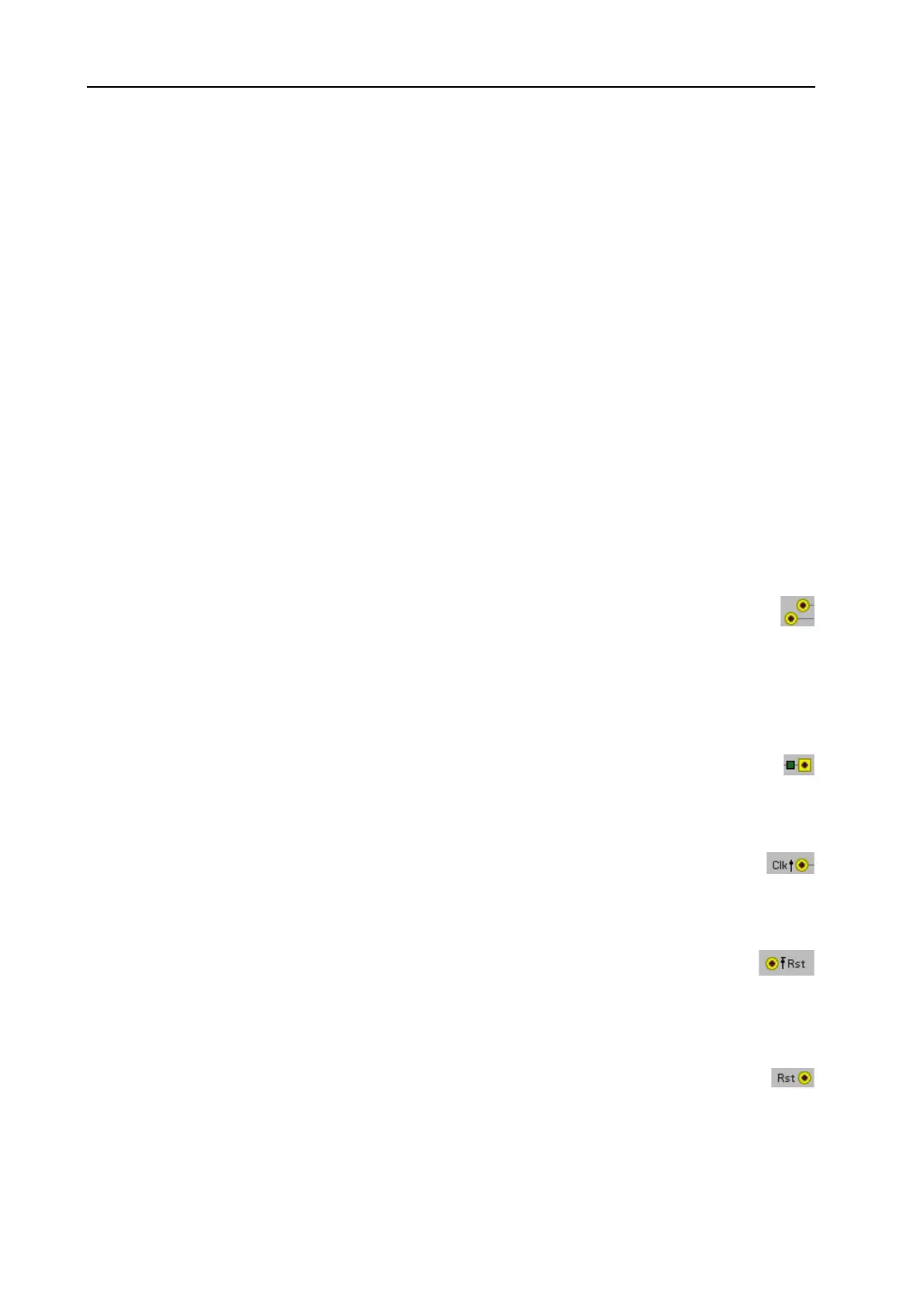
D
ELAYED
ACTION
R
ST
INPUT
Some Rst signal inputs have a barred arrow next to their input connector. This tells that the
module has a delayed function, meaning it will wait for the positive edge on another signal input
before resetting the module. In practice it means that the actual reset is synchronized to the clock pulses
on the Clk input.
R
ST
INPUT
(
LEVEL
CONTROLLED
)
A level controlled Reset signal input has no arrow and is used to reset a module to its initial value
on the moment when a logic
HIGH
reset pulse arrives and then halts or disables the module until
the reset signal has returned to a logic
LOW
level. So, as long as there is a logic
HIGH
level on this input
the module will stay inactive in its default state.
Bekijk gratis de handleiding van Nord Modular G2, stel vragen en lees de antwoorden op veelvoorkomende problemen, of gebruik onze assistent om sneller informatie in de handleiding te vinden of uitleg te krijgen over specifieke functies.
Productinformatie
| Merk | Nord |
| Model | Modular G2 |
| Categorie | Niet gecategoriseerd |
| Taal | Nederlands |
| Grootte | 60689 MB |


