Nord Modular G2 handleiding
Handleiding
Je bekijkt pagina 221 van 291
NORD MODULAR G2 V1.4x 13. Module reference: Switch group
Page 221
SWITCH GROUP
In the Switch group you will find different types of switches for signal routing tasks and Control/Audio
signal multiplexers etc.
C
OMMON
S
WITCH
PARAMETERS
C
TRL
OUTPUT
WITH
D
ISPLAY
BOX
AND
C
TRL
INPUT
The Control output combined with a Display Box is a special feature of the Switch modules.
It’s especially designed to work with the Ctrl Inputs of the Multiplexer modules. As soon as
you activate a Switch module by clicking on a button, for example, the Control output sends
out a control signal offset depending on which button you select. The offset value is also
shown in the Display Box. This control signal offset can then be patched and used to activate the
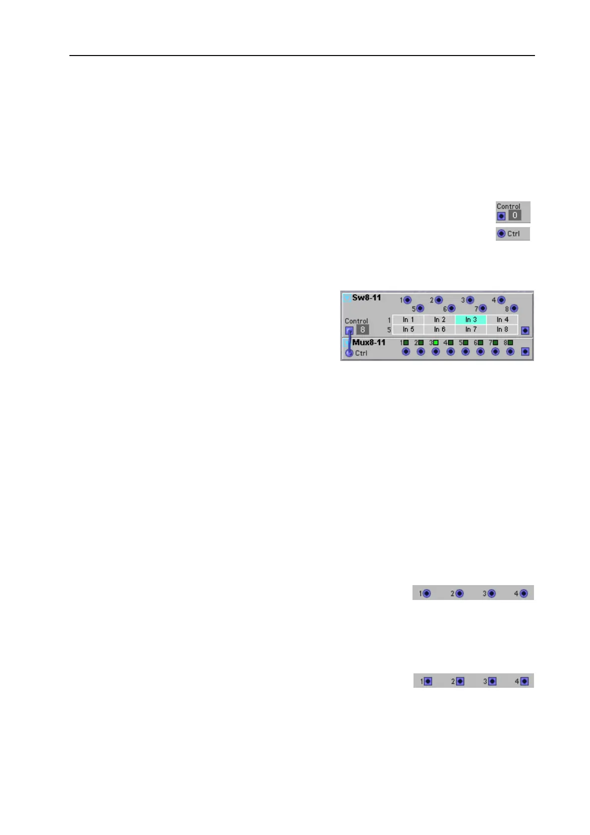
corresponding “channel” in a Multiplexer module. Let’s have a look at the following example:
Let’s say we want to be able to activate the channel in the
1-8Mux module that corresponds to the button we select
in the 8-1Switch module.
1. Connect the Ctrl output of the 8-1Switch to the Ctrl
input of the 1-8Mux.
2. Now, click on the In 3 button of the 8-1Switch and note that the third LED of the 1-8Mux is lit.
3. Click on the In 8 button of the 8-1Switch and note that the last LED of the 1-8Mux is lit instead.
The special thing about this Ctrl signal is that it’s defined by the different “states” of the Switch mod-
ule, i.e. which Channel Select button is currently depressed. The Switch module sends out the Ctrl
signal value 0 for the initial state (no button or button 1 depending on type of Switch module), value
4 for the next state, value 8 for the next and so on. The maximum Ctrl signal value a Switch module
can send is 28 when button number 8 is selected on an 8-1Switch or 1-8Switch module. The Ctrl input
on the 8-1Mux and 1-8Mux modules responds according to these Ctrl signal ranges: 0<4 = channel
1 active, 4<8 = channel 2 active, 8<12 = channel 3 active and so on up to 28 and above, which will
activate channel 8. The reason for this pre-defined Ctrl value ranges is that a Switch module button
should always correspond to the same channel number on a Mux module, regardless of number of
buttons/channels on the module.
I
NPUTS
All Mixer module inputs are D
YNAMIC
C
ONTROL
/A
UDIO
signal inputs.
This means they adapt the module bandwidth to the bandwidth of the
incoming signal(s). As soon as you patch an audio signal to one input, the entire Mixer module will
automatically “update” to Audio bandwidth for highest possible quality. This also results in the module
using more Patch Load.
O
UTPUT
(
S
)
D
YNAMIC
C
ONTROL
/A
UDIO
depending on the input signals. Signal:
B
IPOLAR
Bekijk gratis de handleiding van Nord Modular G2, stel vragen en lees de antwoorden op veelvoorkomende problemen, of gebruik onze assistent om sneller informatie in de handleiding te vinden of uitleg te krijgen over specifieke functies.
Productinformatie
| Merk | Nord |
| Model | Modular G2 |
| Categorie | Niet gecategoriseerd |
| Taal | Nederlands |
| Grootte | 60689 MB |


