Nord Modular G2 handleiding
Handleiding
Je bekijkt pagina 157 van 291
NORD MODULAR G2 V1.4x 13. Module reference: In/Out group
Page 157
N
OTES
ABOUT
USING
THE
A
UDIO
I
N
SOURCES
The ‘In’ selector routes
LINE
LEVEL
audio signals from the I
N
1-4 inputs on the rear panel of Nord
Modular G2 to your patch. You can also use a dynamic microphone in the XLR M
IC
I
NPUT
on the rear
panel. This input has a built-in preamp and you control the input gain with the M
IC
G
AIN
knob on the
front panel. If you use a dynamic microphone in the XLR M
IC
I
NPUT
, make sure no cable is connected
to the L
INE
I
N
1 jack on the back of the G2. The M
IC
I
NPUT
signal can then be patched from the Out
1 (or L) output of the Input modules. A total of four separate audio signals can be patched into the system
at a time.
If you use the I
N
1-4 inputs it’s important that you amplify the input signals to line level externally to get
good sound quality. If you put in too low a signal and amplify it, using for example the Pad scroll button
or the Amplifter module, the sound quality won’t be good. The reason for this is that the internal
amplification is digital, and a low analog input signal will result in low resolution. A low resolution signal
that is digitally amplified will have a LoFi sound quality.
Note: If you want to process a stereo input signal, remember taht almost all modules have only one mono
input. This means that any processing modules (filters etc.) have to be duplicated in the patch, one for
the Left channel and another one for the Right channel.
P
AD
The Pad scroll button on the Input and Output modules can be used to attenuate or
amplify the signals. On the Input modules you can select between 0dB, -6dB, -12dB and
+6dB and on the Output modules between 0dB and +6dB.
O
N
/O
FF
Click the On/Off button to mute the signal(s) of the In/Out module. Blue color indicates ‘On’ and
gray ‘Mute’.
L
EVEL
METERS
The level meters on the Input modules displays the following signal levels: green
LED
s
between -40dB and 0dB, yellow
LED
s between >0dB and +11dB and red
LED
at >11dB.
Tip! Level meters can be assigned to frontpanel knobs with a right mouse click on the level
meter. This will cause the
LED
s around the knob to act as a (circular)
VU
-meter.
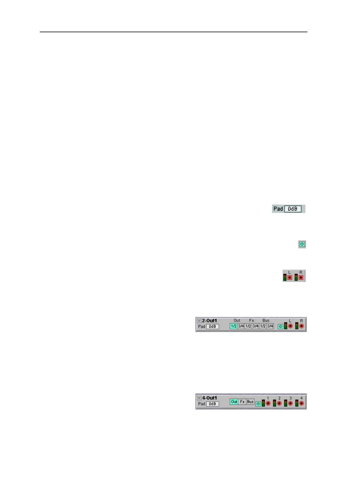
2-O
UT
This module is used to patch stereo signals to the Audio
Outs, the FX Area or the audio Buses.
S
OURCE
SELECTOR
BUTTONS
Here you select the signal destination: Audio Out channels 1/2 or 3/4, FX Area channels 1/2 or 3/4 or
audio Bus channels 1/2 or 3/4. Note that it makes no sense to use the FX channels when the module is
in the FX Area, in fact the FX channels are disabled when this module is placed in the FX Area.
To read more on signal routing check out "Common In/Out module parameters and definitions”.
4-O
UT
This module is used to patch individual signals to
different destinations: the Audio Out, the FX Area or
the Global Buses.
Bekijk gratis de handleiding van Nord Modular G2, stel vragen en lees de antwoorden op veelvoorkomende problemen, of gebruik onze assistent om sneller informatie in de handleiding te vinden of uitleg te krijgen over specifieke functies.
Productinformatie
| Merk | Nord |
| Model | Modular G2 |
| Categorie | Niet gecategoriseerd |
| Taal | Nederlands |
| Grootte | 60689 MB |


